Hamann Manus · Volume 4
Theory of Operation: How the Switching Latch Works
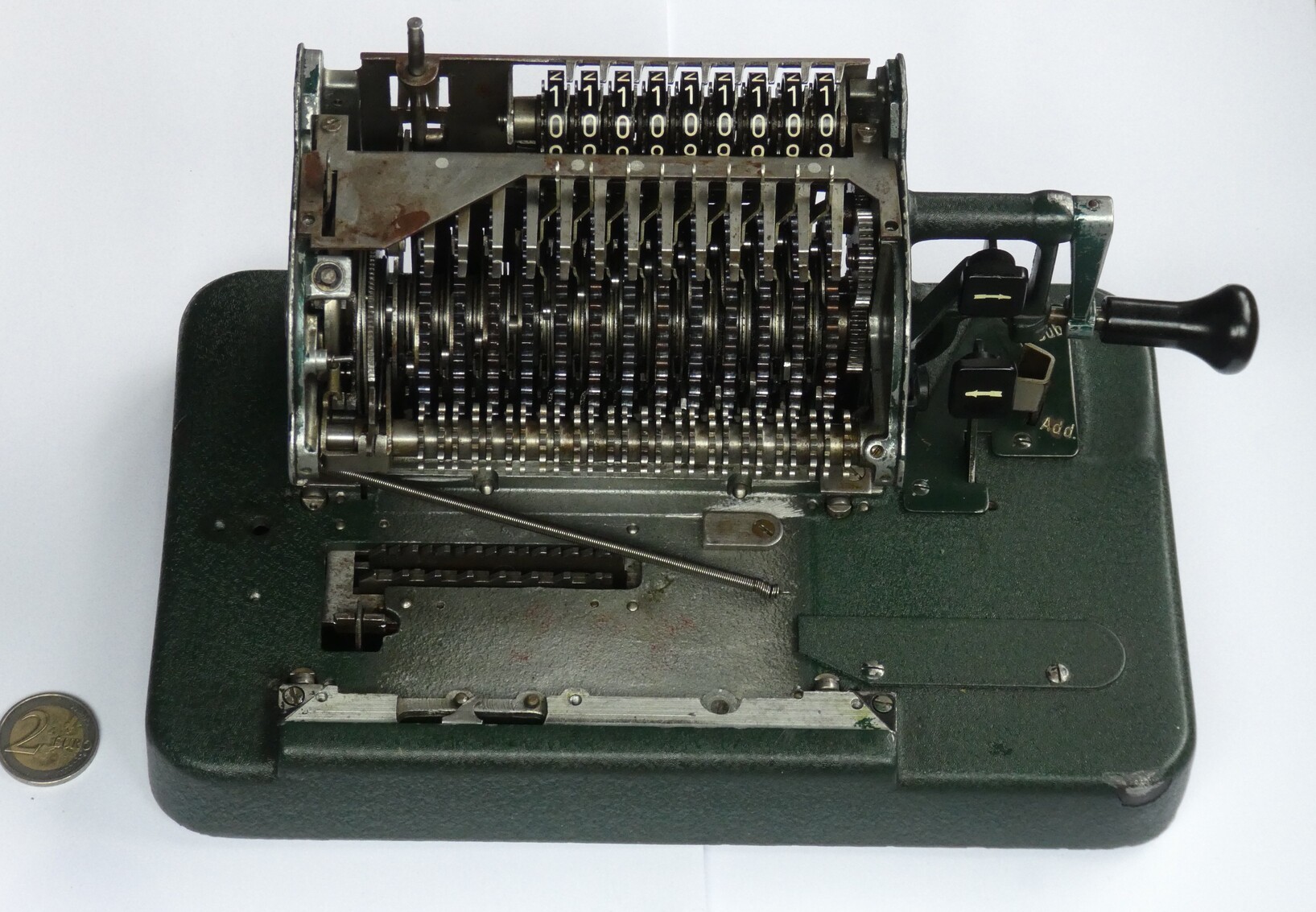
Every hand calculating machine of the 1920s solves the same problem: turn the crank once, and the number set on the levers must be added into the result register, each decimal place moving its result wheel by exactly the digit set for it, with tens carried from place to place. A pinwheel machine does it with wheels whose teeth slide out by the amount of the digit. A stepped-drum machine uses a drum of nine teeth of different lengths and a sliding pinion. Hamann’s Manus does it differently again. Each place has a toothed wheel loose on the crank shaft, and a spring latch that couples the wheel to the shaft for a stretch of the turn, through a gap whose length the setting lever controls. A setting of 4 opens a gap four teeth long. The latch drops in, drives the wheel four teeth, and lifts out again.
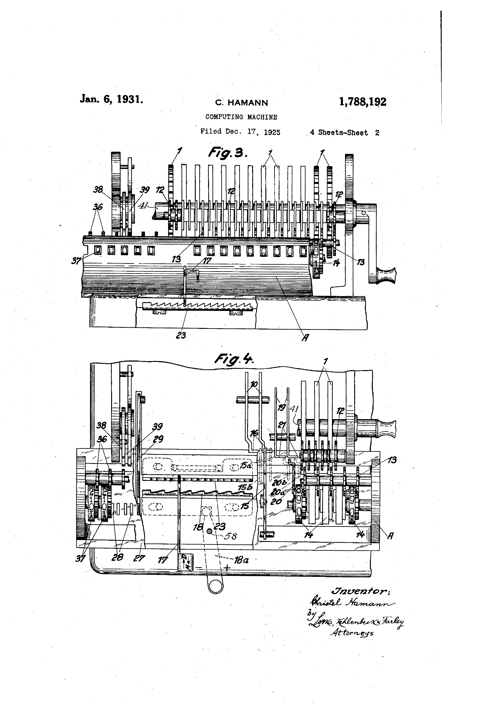
This volume follows that principle through the whole machine: the drive, the tens carry, adding and subtracting with one crank direction, the counter, the carriage, automatic division, clearing and the safety locks. The part names and reference numbers are those of Hamann’s US patent 1,788,192 (“Computing Machine”, filed 17 December 1925, granted 6 January 1931; the English twin of DE 432,435), so the drawings here and the patent sheets can be read side by side.
4.1 One place of the drum
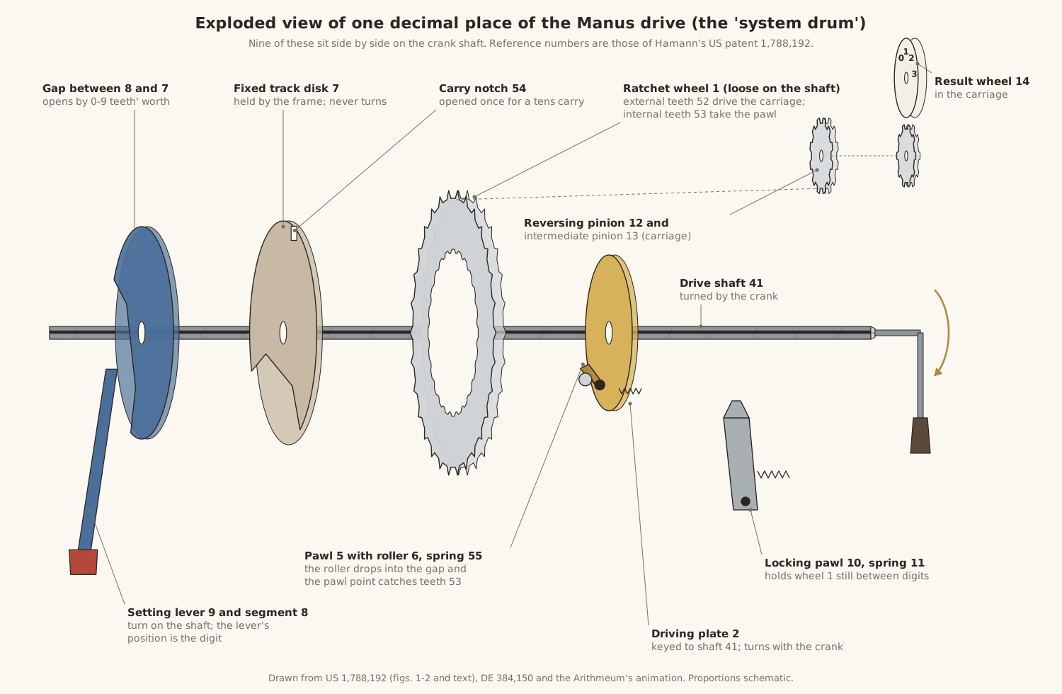
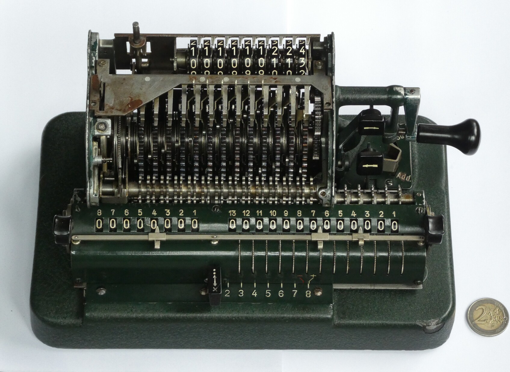
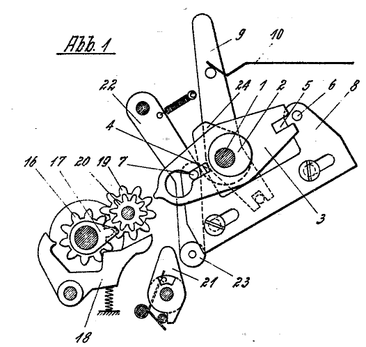
The nine decimal places of the input sit side by side on the drive shaft 41, which the crank turns. Together they make what the factory called the Systemwalze, the system drum. Each place is a closed sub-assembly of six main parts.
Table 1 — One place of the drum
| Part | No. | What it is | What it does |
|---|---|---|---|
| Setting lever | 9 | the slide the operator moves, with its red or white cap | turns the setting segment to the digit |
| Setting segment | 8 | a plate turned on the shaft by the lever, not by the crank | forms one side of the gap |
| Fixed disk | 7 | a plate held by the frame; it never turns | forms the rest of the track; carries the carry notch 54 |
| Ratchet wheel | 1 | a wheel loose on the shaft, with external teeth 52 and internal teeth 53 | the wheel that is driven; its outer teeth drive the carriage |
| Driving plate | 2 | a plate keyed to the shaft; turns with the crank | carries the pawl round |
| Pawl, roller, spring | 5, 6, 55 | a spring-loaded latch with a roller that runs on the track | couples plate 2 to wheel 1 while the roller is in the gap |
| Locking pawl | 10 (spring 11) | a detent on the frame | holds wheel 1 still whenever it is not being driven |
4.1.1 How a setting becomes a number of teeth
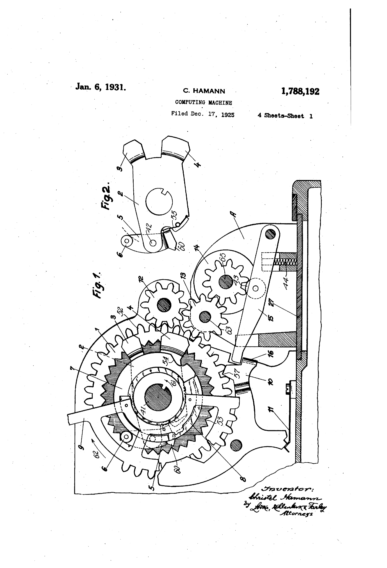
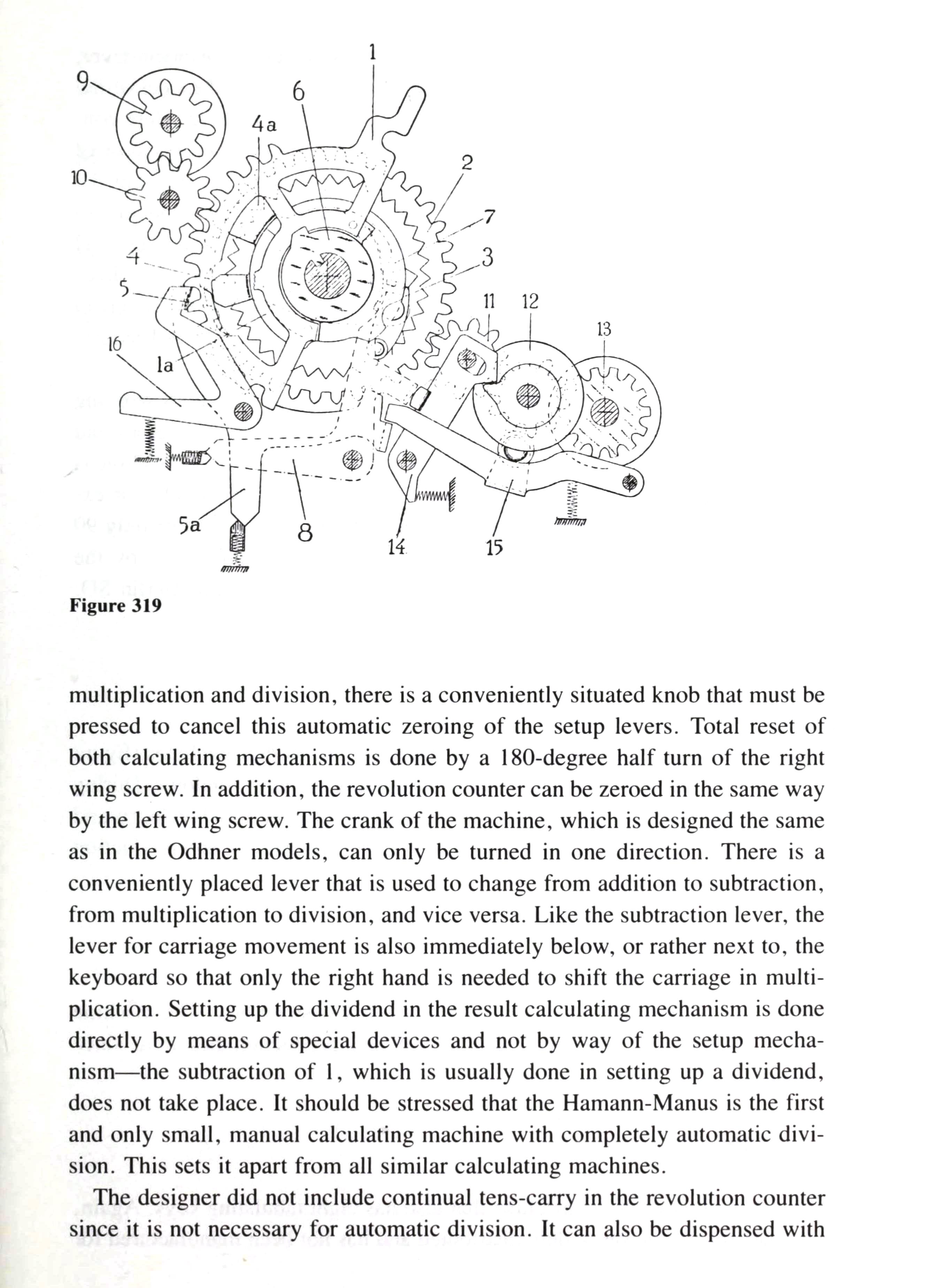
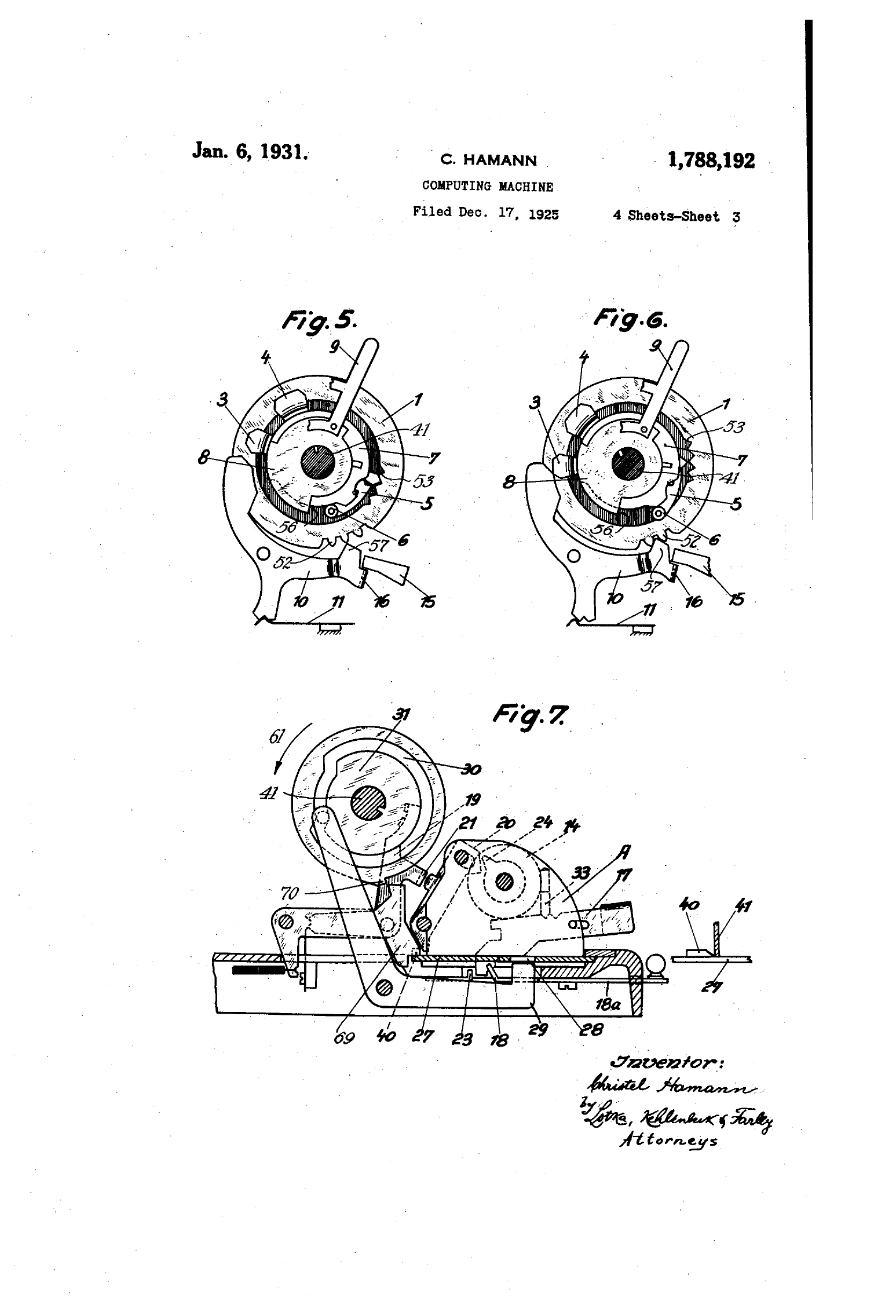
The roller 6 on the pawl runs round a track made of two edges, the edge of the fixed disk 7 and the edge of the setting segment 8. The patent describes what happens at zero and at any other digit:
When the handle or lever 9 is brought to the zero position, the edges of the stationary disk 7 and of the segment 8 constitute together a continuous or closed track … [for digits 1–9] a gap 56 … is formed in said continuous track owing to the fact that the edges of the disk 7 and the segment 8 become separated more or less.
While the roller rides on the track, the pawl is held out, clear of the ratchet wheel’s internal teeth, and the wheel stands still. When the roller reaches the gap, the spring 55 pushes it in:
… the spring will force the roller 6 inwardly into the gap, thus swinging the pawl 5 … into engagement with the internal teeth 53 of the respective ratchet wheel 1, and from that moment on such ratchet wheel will rotate in unison with the shaft 41, for a period of time corresponding to the circumferential extent of the gap.
At the end of the gap the roller climbs back onto the track, the pawl lifts out of the teeth, and the wheel stops. The gap is as long as the digit, measured in teeth, so the wheel has moved exactly that many teeth. A setting of 0 leaves the track closed, the roller never drops, and nothing is transferred.
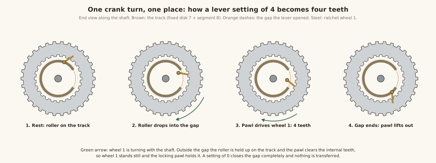
Christian Hamann, a Berlin collector of these machines (and, as far as is known, not a relation of the designer), drew the same cycle in colour, with his own letters for the parts: lever L, movable plate M, fixed plate F, gap G, hook H, sensor S and wheel T.
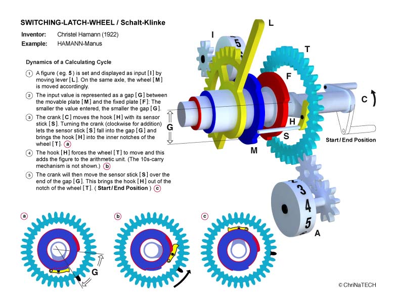
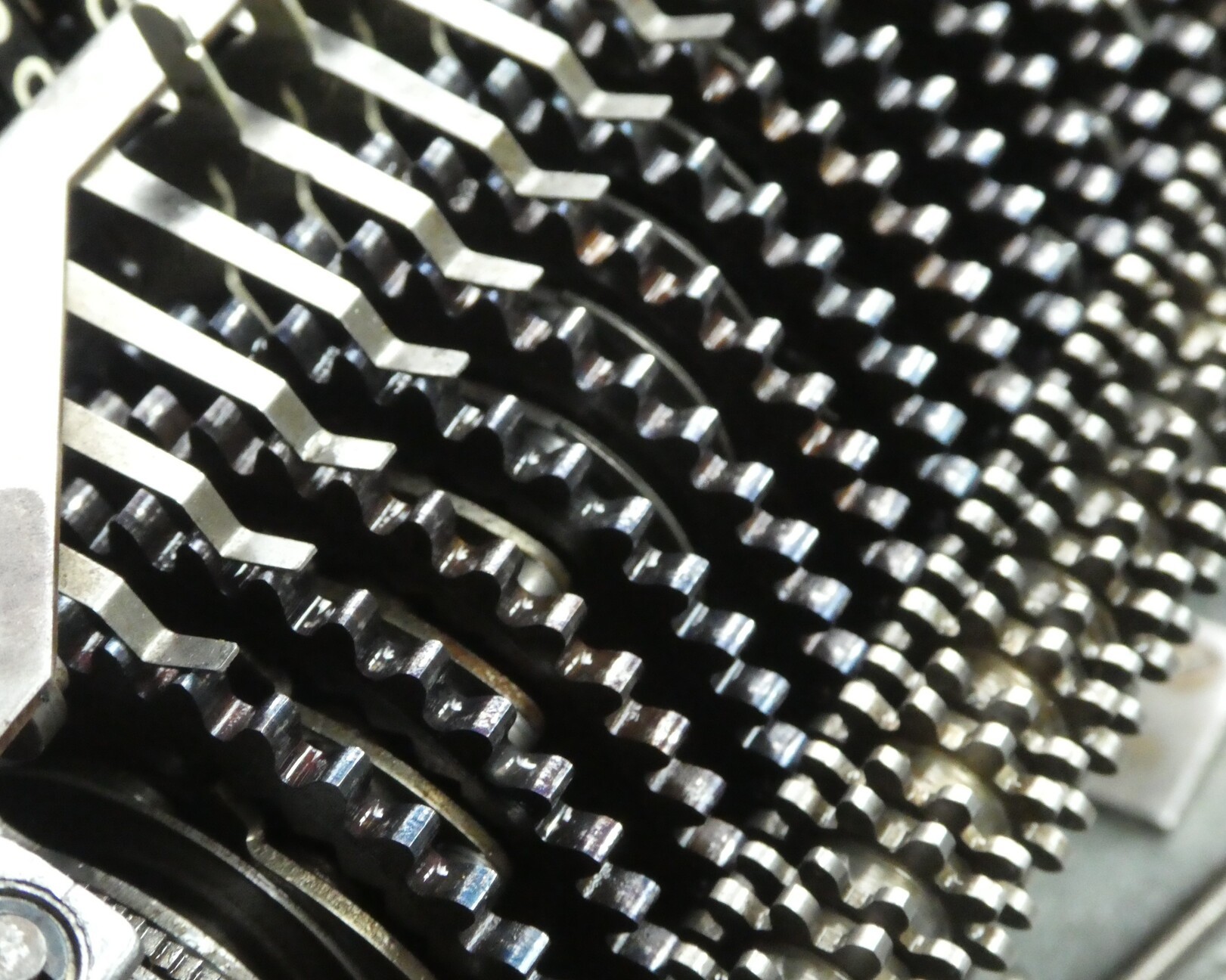
The ratchet wheel’s external teeth 52 pass the movement on to the carriage. The real wheel is a single steel part, toothed inside and out. Ernst Martin, in 1925, counted 36 teeth on each side.
4.1.2 Holding still: the locking pawl
A wheel that has just been driven four teeth must stop dead and stay there. That is the job of the locking pawl 10. At rest a tooth 57 on it locks wheel 1. When the wheel starts to move, the pawl is pushed out and held clear by its spring 11. After the roller has left the gap, a lug 3 on the driving plate pushes the locking pawl back into place. The patent points out that the locking lever “does not drop into place tooth by tooth”, which avoids noise and wear. The 1923 patent added trailing locks “to cancel inertia” at speed. That is the Manus’s answer to overthrow, the fault of a wheel coasting past its digit, and Martin praised its “fully automatic silent movement” for preventing it.
4.1.3 The spiral: one place after another
The nine driving plates are not lined up on the shaft. Each is turned a little further round than the one before, so the pawls form a spiral. The 1920 patent says the latches “form spirals”. The factory repair manual for the later Automat S, which uses the same system, gives the figure: each place is set 12° further round than its neighbour, and shims keep the places exactly 8 mm apart. The effect is that the units place is driven first, then the tens, then the hundreds, through each turn of the crank. The work is spread over the turn, so the crank runs lightly, and each place has finished before the next begins. That is what makes the tens carry possible.
4.2 The tens carry
On a Manus the tens carry is made by the drum, not by the carriage. The fixed disk 7 of each place has, besides the main stretch of track, a small notch 54. It is normally covered. When a result wheel in the carriage passes from 9 to 0, or from 0 to 9 when subtracting, a carry lever in the carriage pushes a part the factory called a Blendenöffner, a “shutter opener”, which uncovers the notch of the next place up. When that place’s roller comes round, it drops into the notch for one tooth, and the next result wheel moves on by one. Near the end of the turn a bead on the driving plate closes the notch again. The patents describe the notch and the drum side clearly. The exact linkage from a result wheel in the moving carriage to the shutter opener of the fixed drum above it is not spelled out in any source I have read; the repair manual mentions only “carry levers in the carriage” pressing the shutter openers, with at most 0.1 mm of play.
The 1920 patent describes it: “The latches transmit the set values and also the tens.” Because the places are driven one after another up the spiral, a carry set up by the units place is ready before the tens place’s latch arrives. A chain of carries, as in 999,999,999 + 1, therefore ripples all the way along within a single turn.
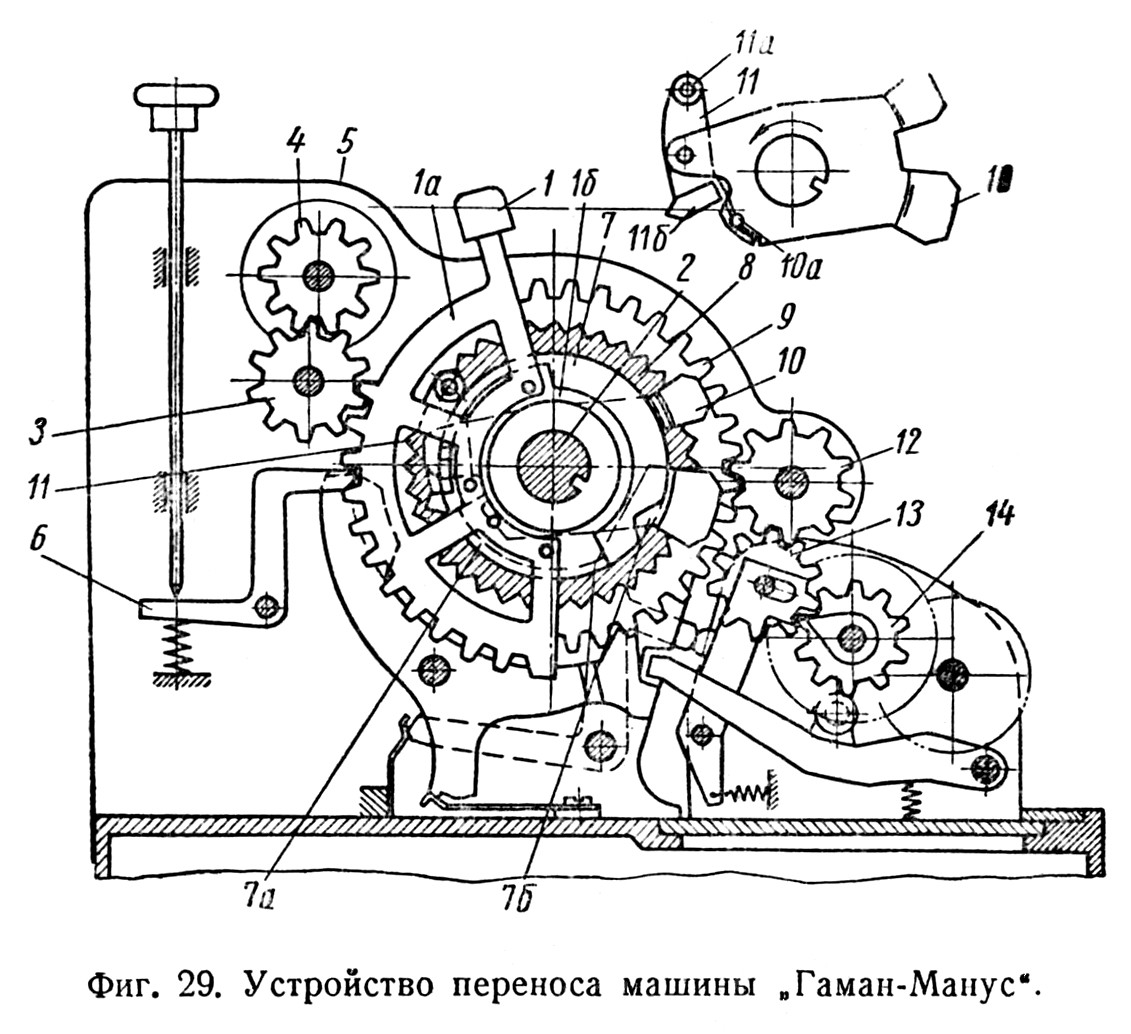
The factory repair manual names the two classic result-register faults after this mechanism. An Auslassfehler is a skipped carry, too little added; a Schleuderfehler is overthrow, too much. The volume on repair comes back to both.
4.3 Adding and subtracting with one crank direction
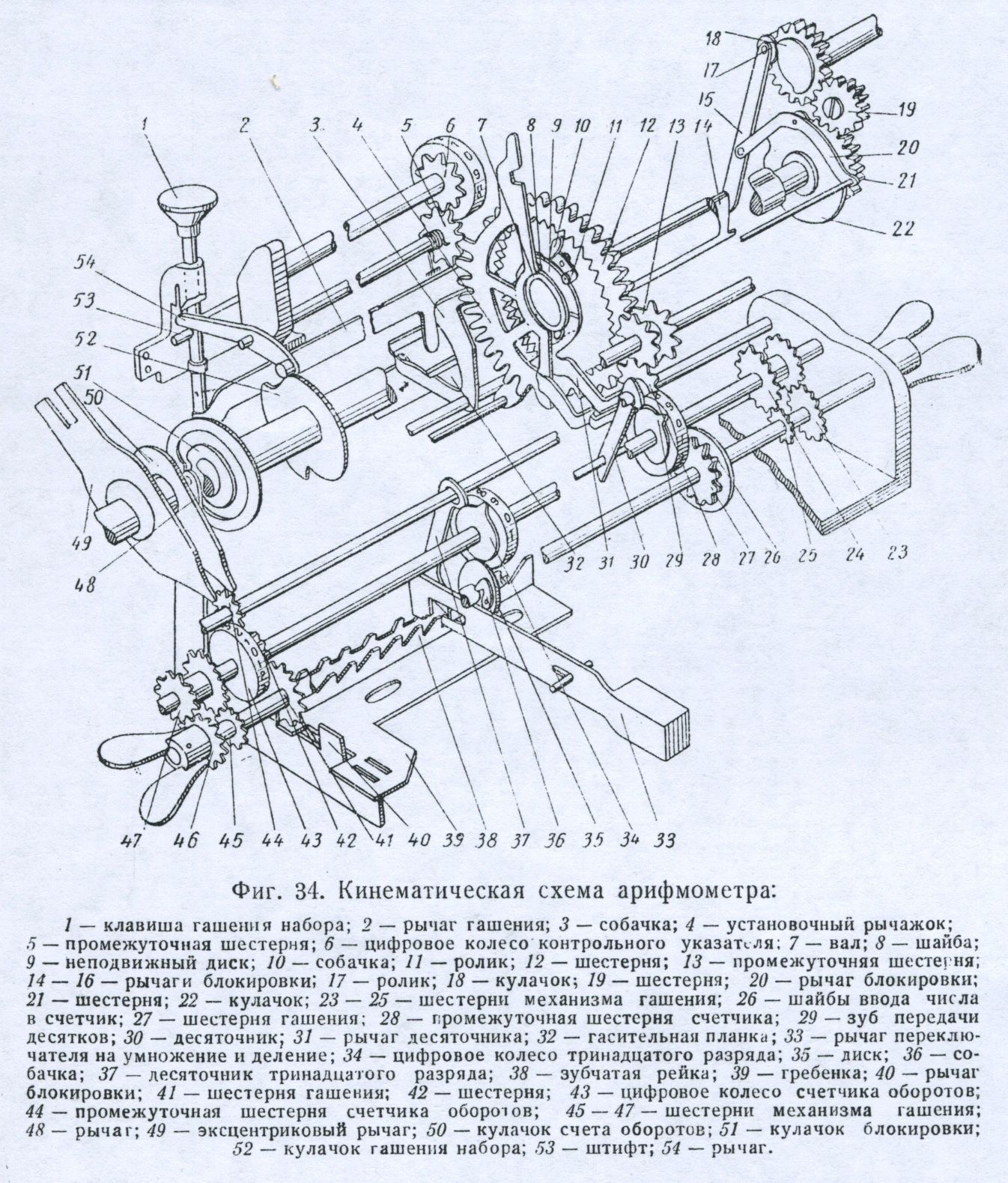
On a pinwheel machine you subtract by turning the crank backwards. On the Manus the crank always turns clockwise, and a small lever under the crank chooses add or subtract. It works by moving the carriage sideways.
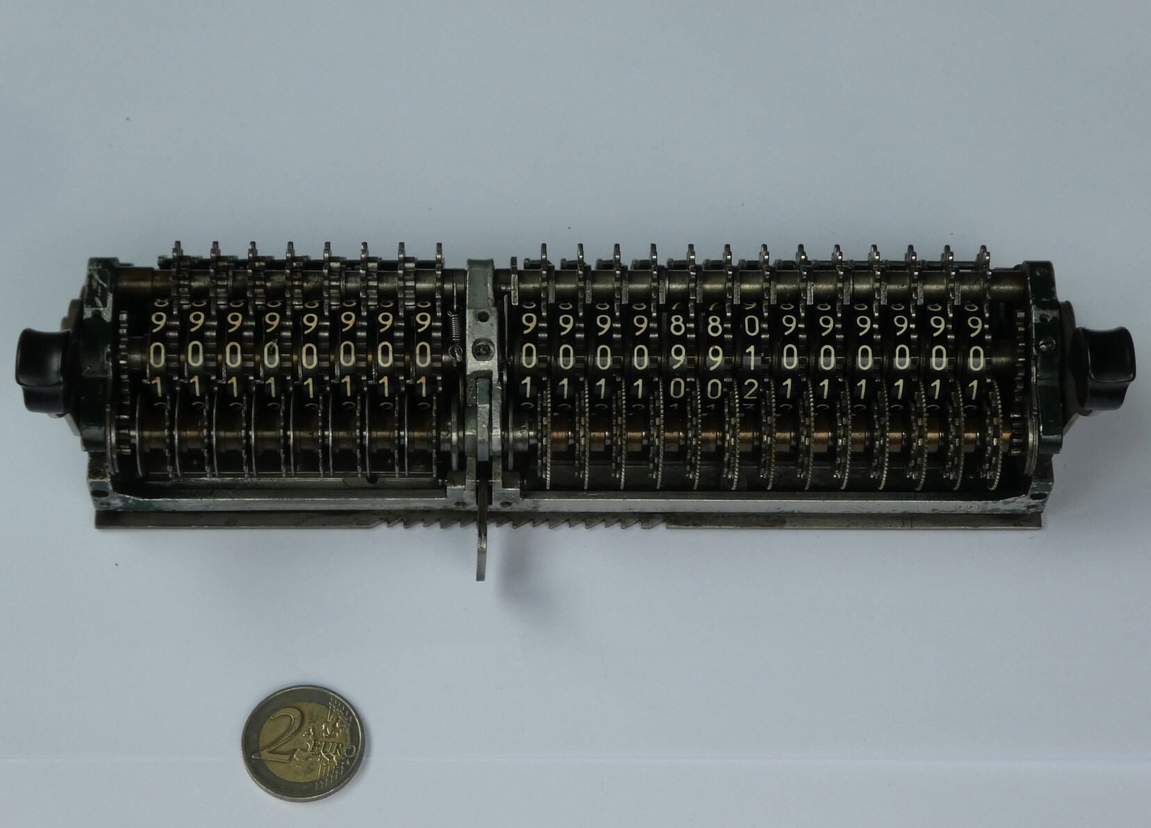
The external teeth of each ratchet wheel 1 mesh permanently with a pair of twin pinions. The carriage carries, for each place, an intermediate pinion 13 and the result wheel 14. The patent explains that each twin pinion 12 and each intermediate pinion 13 “is half as thick as a ratchet wheel 1”. When the Add/Sub lever moves the carriage half a place sideways, the intermediate pinions change partners:
- Add: each intermediate pinion 13 meshes the ratchet wheel directly, and the result wheel 14 turns forwards.
- Sub: the intermediate pinion meshes the other half of the twin pinion 12 instead. One more gear in the train reverses the direction, and the result wheel turns backwards.
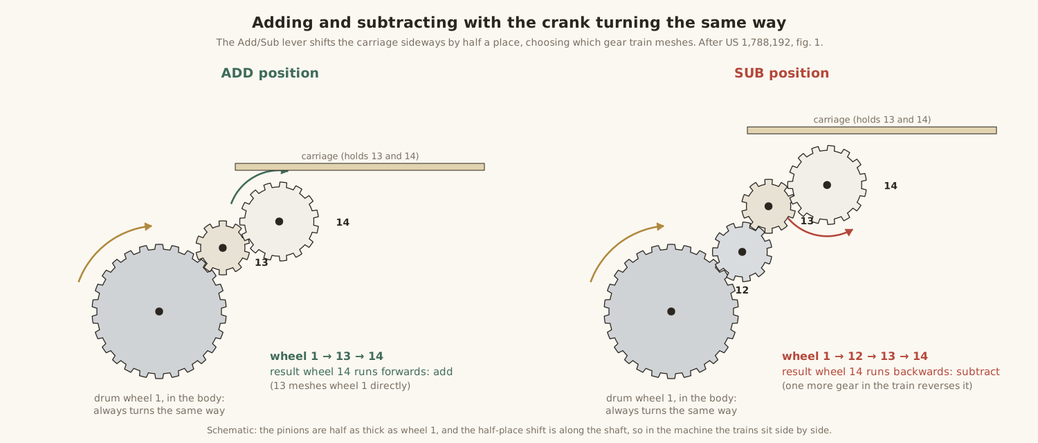
That is why the carriage scale on later models has two pointers for each position, a white plus arrow and a red minus arrow: the carriage really does sit in two slightly different places. The first patents of 1920–23 had done it differently, with two latches per place, one for each crank direction. The single direction with a reversing gear arrived with the automatic-division patent of 1924, because automatic division needs it.
4.4 The revolutions counter
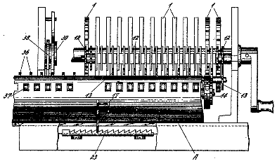
The counter counts crank turns. An eccentric on the shaft works a single-tooth finger (Einzahn) that advances the counter wheel in the carriage’s current position by one at every turn. DE 443,479 made it reversible by letting a control lever, the counter lever with its ”+” and ”−” marks, hold the two-armed finger on one side or the other.
The factory manual explains what the lever does, and it is easy to misread. It does not choose whether the counter adds or subtracts. It chooses whether the counter runs in the same sense as the result register or the opposite sense:
When the counter control lever is in the ”+” position, the units rotate in the same direction, either both positive or both negative. If … ”−”, the units rotate in opposite direction.
So with the lever on ”+”, the counter counts up when you add and down when you subtract. That is what you want in multiplication, where the counter shows the multiplier. With the lever on ”−”, every subtracting turn counts up, which is what you want in division, where the counter builds up the quotient. The counter’s direction follows the Add/Sub shift of the carriage automatically. The repair manual explains why: the two counting fingers lie side by side, so moving the carriage sideways changes which one engages.
The counter’s tens carry arrived with the model B (DE 468,275). Each counter wheel has a cam that pushes the next wheel a little more than half a step, and a detent completes the step, so several simultaneous carries do not fail through play. The model A’s counter had no carry at all. Martin’s 1925 account says this was deliberate, since automatic division does not need it. But it does matter for short-cut multiplication, which the operating volume explains.
On my machine the lever at the front left, marked ”+” and ”−”, is most likely this counter lever. On some model C’s a lever in that place is a transport lock. Working it with the bottom pan off will settle which it is.
4.5 The carriage
The carriage slides sideways on a guide; it is not lifted, as on an Odhner. A spring pulls it constantly to the left, towards position 1. A latch 17 on the carriage engages a rack 18 in the frame, one tooth per decimal place, and holds it in position. To multiply by a three-digit number you move the carriage to position 3. After each digit a release lever lets the spring move it one place left.
On a model C the carriage is moved by transport levers at the front, with a hook-shaped lever at the left for moving it right. The long double spring that pulls it left is the one that runs across the top of the base in my photograph of the underside.
4.6 Automatic division
This is the feature that made the Manus famous. The operator sets the divisor on the levers and the dividend in the result register, pulls the carriage fully to the right, puts the division lock in, and simply turns the crank until the machine stops. The quotient appears in the counter and the remainder in the result register.
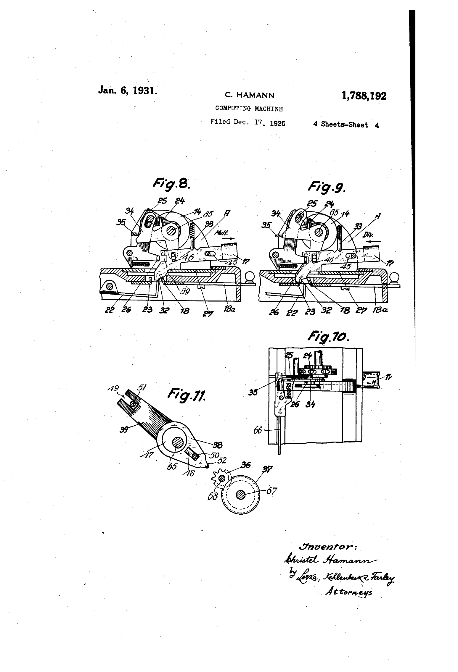
It works with a second rack, 23, which has two teeth for every decimal place. Each half-place is either the subtracting or the adding position of a place. The sequence the patent describes runs like this:
- The carriage starts at the far right in the subtracting position. Each crank turn subtracts the divisor, and the counter counts each turn.
- When the divisor has been subtracted once too often, the leftmost active result wheel passes from 0 to 9. A projection 24 on that wheel strikes a lever 25. The lever briefly withdraws the latch from rack 23, and the spring moves the carriage one tooth, half a place, into the adding position of the same place.
- The next turn adds the divisor back once, which undoes the extra subtraction. The leftmost wheel now passes from 9 to 0, the projection trips the lever again, and the carriage moves another half-place, into the subtracting position of the next place down.
- This repeats, place by place, until the carriage reaches its base position. A locking lever 69 then blocks the crank, “the operator thus becomes aware that the division has been completed.”
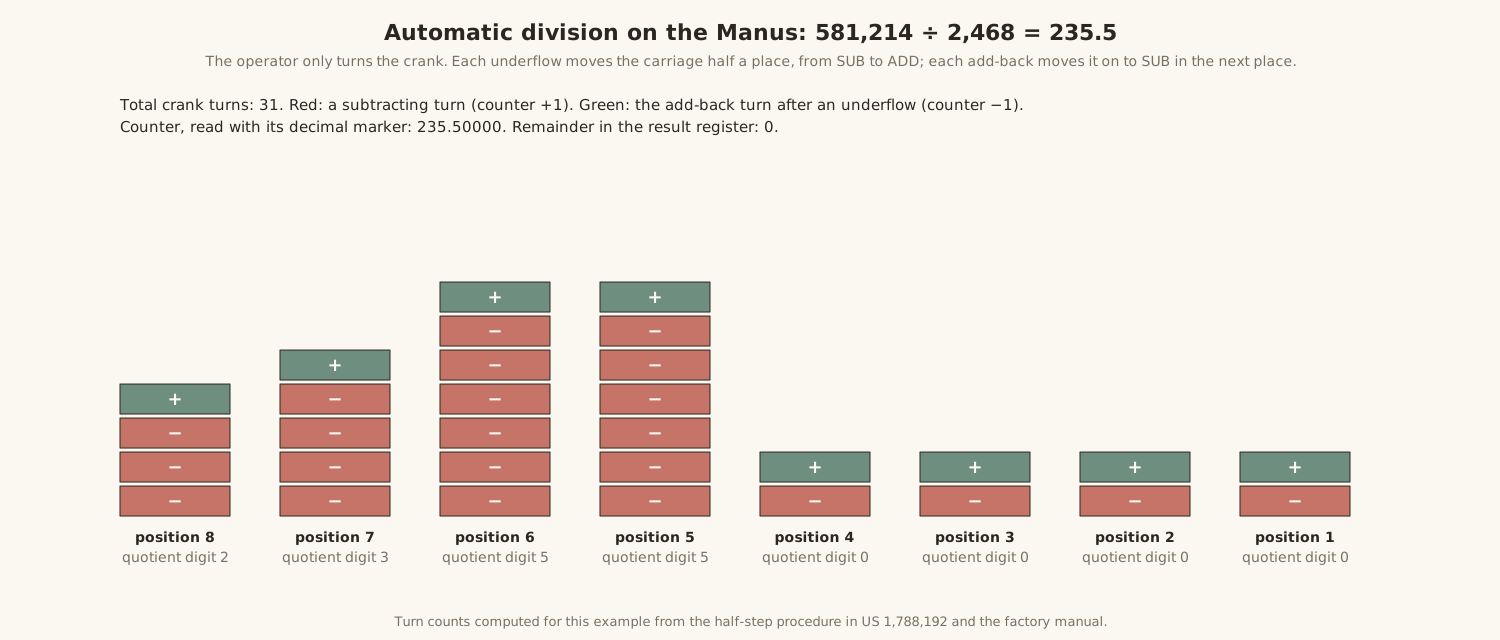
It is ordinary restoring division, the method an operator would follow by hand on a pinwheel machine. On the Manus the machine itself notices the overdraft and moves the carriage. Two details make it reliable. A safety lever 29 riding in a cam groove keeps the carriage from jumping until the shaft is back at rest. And the pawls can only engage after the shaft has turned a little from its rest position, which gives the carriage time to complete its jump before the next transfer begins. On the A and B, the overflow bell is switched out during division, so that it does not ring every time the machine overdraws on purpose.
4.7 Clearing
The setting levers. The knurled knob on top clears them: pressing it lifts the detents that hold each segment, and springs return every lever to zero. The knob also turns, but only while it is held down, to Add or Mult. On Add the levers clear themselves automatically after every crank turn, which is what you want when adding a column of different figures. On Mult the setting stays, which is what you want in multiplication. The “Add.” and “Mult.” legends on the front of my machine mark this knob’s two settings. The F and R replaced the knob with a clearing bar.
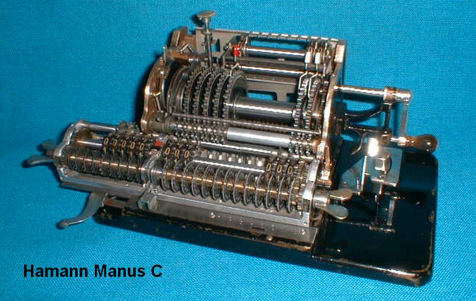
The result register and counter on a model C. These are cleared by the wing nuts at the ends of the carriage, but only in the clearing position, with the carriage pushed to its extreme left, beyond position 1. There, as the patent explains, the locking members that normally hold the result wheels are freed, and the wheels can be turned by hand to zero. Turning the right wing nut, which Martin says needs half a turn, clears the counter and the result register together. The left wing nut clears the counter alone. Christian Hamann’s notes on his C add that pressing the metal tongue in the middle while turning the right wing clears the result register alone. Each wheel is stopped at zero by its own stop, so a quick turn does not overshoot. One collector notes an interlock on the C: the carriage cannot be brought out of the clearing position without clearing the result register.
Setting the dividend. In the same clearing position, thumbwheels let the operator set a number directly into the result register, which is how a dividend is entered for division. They can only be turned when the register is disengaged from the drum, and must not be turned past 9 or 0.
4.8 The crank and the safety locks
The crank rests in a holder at its zero position and locks there. To turn it you pull the handle out of the holder, turn it clockwise, and let it snap back in at the end of the turn. It cannot turn backwards. From the model B a small release tab lets you back it out if the machine jams part-way through a turn. The factory manual insists that this is the only time it may be turned the other way.
The machine is full of interlocks, and the factory manual states the rules that follow from them:
The “Hamann Manus” is equipped with various enforced locks and safety features that are activated when operating errors occur. In such cases no form of force should be used to release the locks. … No operating controls should be moved while the crank is being turned. An erroneous crank turn should always be carried through to the end.
The most important lock for a repairer is the one the Automat S repair manual describes: if the drum has stopped part-way round, off its zero position, a safety slider drops into a safety rail and the carriage cannot be moved either. A Manus that seems seized in every direction may only be stopped mid-turn, and the repair volume explains how to free it.
4.9 Putting it together: one multiplication
Set 3,845 on the levers and turn the knob to Mult, put the Add/Sub lever on Add, the counter lever on ”+”, and the carriage in position 3.
- Two turns in position 3. In each, the units place of the drum moves its wheel 5 teeth, the tens place 4, the hundreds 8, the thousands 3, one after another up the spiral. The carriage, three places to the right, receives them as hundreds, thousands, ten-thousands and hundred-thousands. Any carries set up on the way ripple up through the notches 54 within the same turn. The counter’s third place counts 1, then 2.
- Release one place left; four turns. The same transfers, one decimal place lower.
- Release again; six turns. The counter reads 246 and the result register 945,870, which is 3,845 × 246.
Twelve turns of the crank and two releases of the carriage. The machine does everything else.
Comments (0)