Planimeters · Volume 3
Theory of Operation: How Two Arms and a Wheel Measure Area
It seems impossible at first. The tracer goes round an irregular shape; the wheel rolls forward and back, skids, sometimes spins quickly, sometimes hardly at all; and yet at the end its net roll is exactly proportional to the area enclosed, whatever the shape and wherever the pole was put. This volume explains why, following the proof in K&E’s own manual (pages 29–31), and then the neutral circle and what “compensating” actually cancels.
3.1 The one key fact
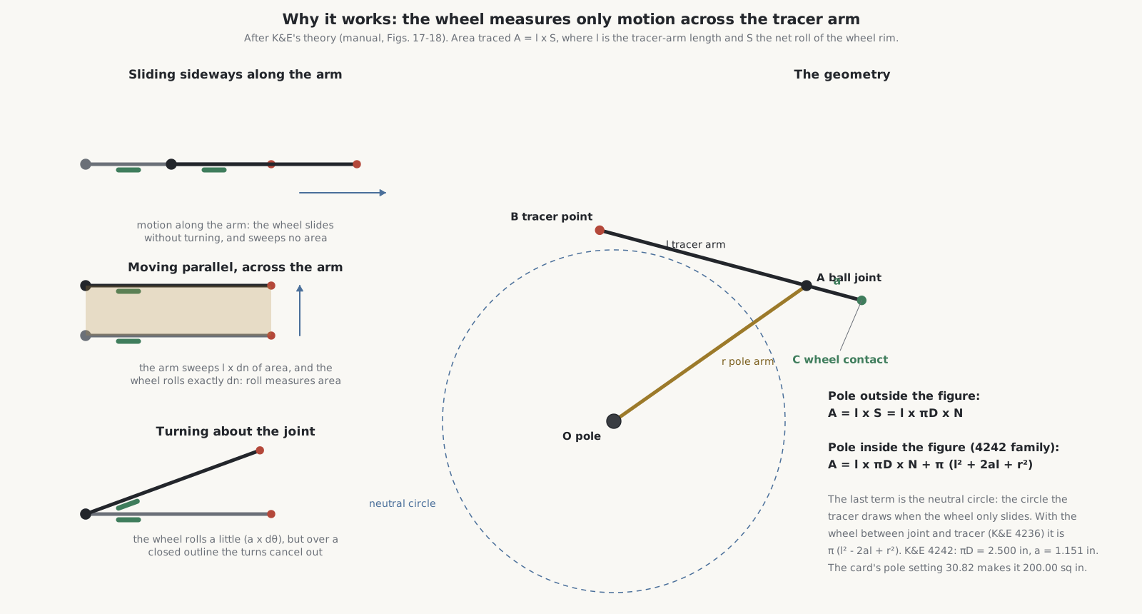
Pick up the tracer arm and carriage and try it, as K&E’s manual suggests: swing the carriage round the tracer point and the measuring wheel turns rapidly; move it straight along the line of the tracer arm and the wheel slides without turning. The wheel’s axle is parallel to the tracer arm, so the wheel rolls only for motion across the arm, never for motion along it. “This characteristic sliding or turning of the measuring wheel,” the manual says, “is the key to the planimeter performance.”
3.2 The proof
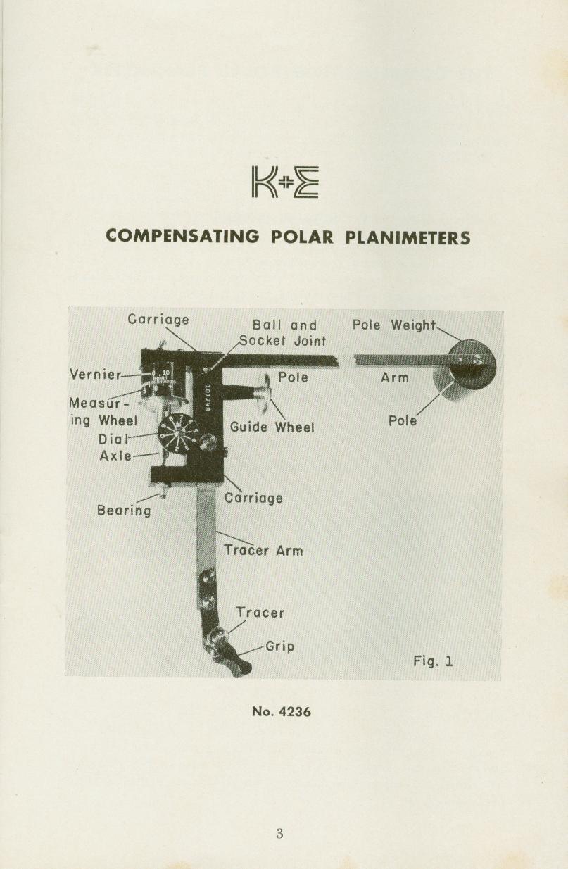
Call the pole O, the ball joint A, the tracer point B and the point where the wheel touches the paper C. The pole arm OA has length r, the tracer arm AB length l, and the wheel sits a distance a from the joint.
Any small movement of the instrument can be split into three parts: the tracer arm moves parallel to itself a perpendicular distance dn; it swings about the joint through a small angle dθ; and the pole arm swings about the pole through dφ. The area swept by the two arms is
dA = l dn + ½ l² dθ + ½ r² dφ
The wheel rolls the full parallel shift dn, plus a dθ from the swing, so its rim moves
dS = dn + a dθ
Substituting for dn:
dA = l dS − a l dθ + ½ l² dθ + ½ r² dφ
Now add these up all the way round the outline, back to the starting point:
A = l S + (½ l² − a l) ∮ dθ + ½ r² ∮ dφ
where S is the net distance the wheel rim has rolled.
With the pole outside the figure, neither arm makes a complete turn: each swings out and back, and its net angle is zero. Both integrals vanish, and
A = l × S
The area is the length of the tracer arm times the net roll of the wheel. It does not depend on the length of the pole arm, on where the wheel sits, or on where the pole was placed. If the wheel’s circumference is πD and it turns N times, A = l πD N: for a given setting the area is simply proportional to the wheel’s revolutions, which is what the dial, wheel and vernier count. On the 4242 family πD is 2.500 inches, so with the tracer arm at the card’s 20.38 (4.012 inches) one turn of the wheel is 10.03 sq in, adjusted to exactly 10 for this instrument.
3.3 The neutral circle
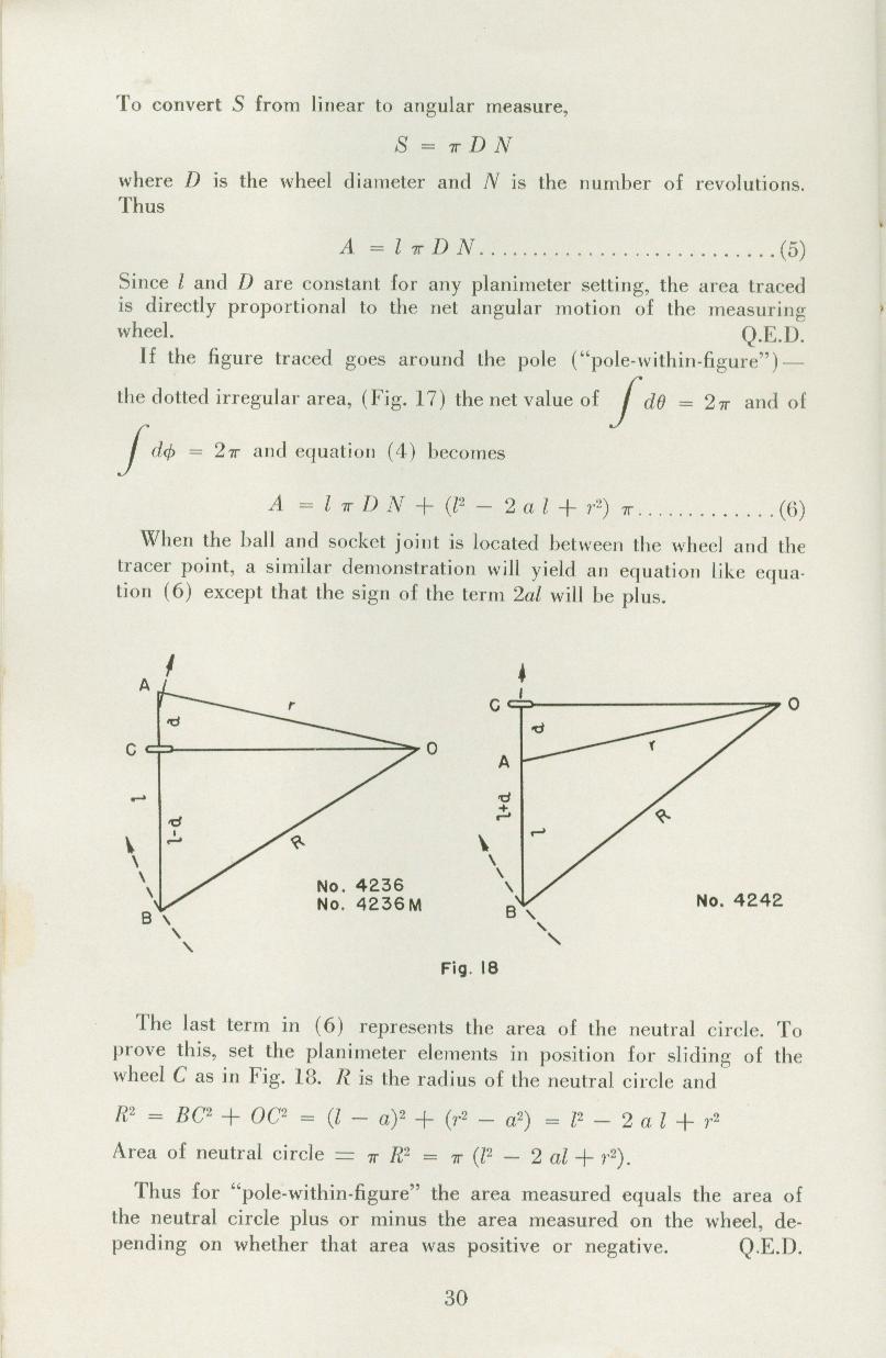
With the pole inside the figure, both arms go right round once, so each integral is 2π, and
A = l πD N + π (l² + 2al + r²)
on the 4242 family, whose ball joint lies between the wheel and the tracer point. (On an instrument like the fixed-arm K&E 4236, with the wheel between the joint and the tracer, the sign of 2al is negative.)
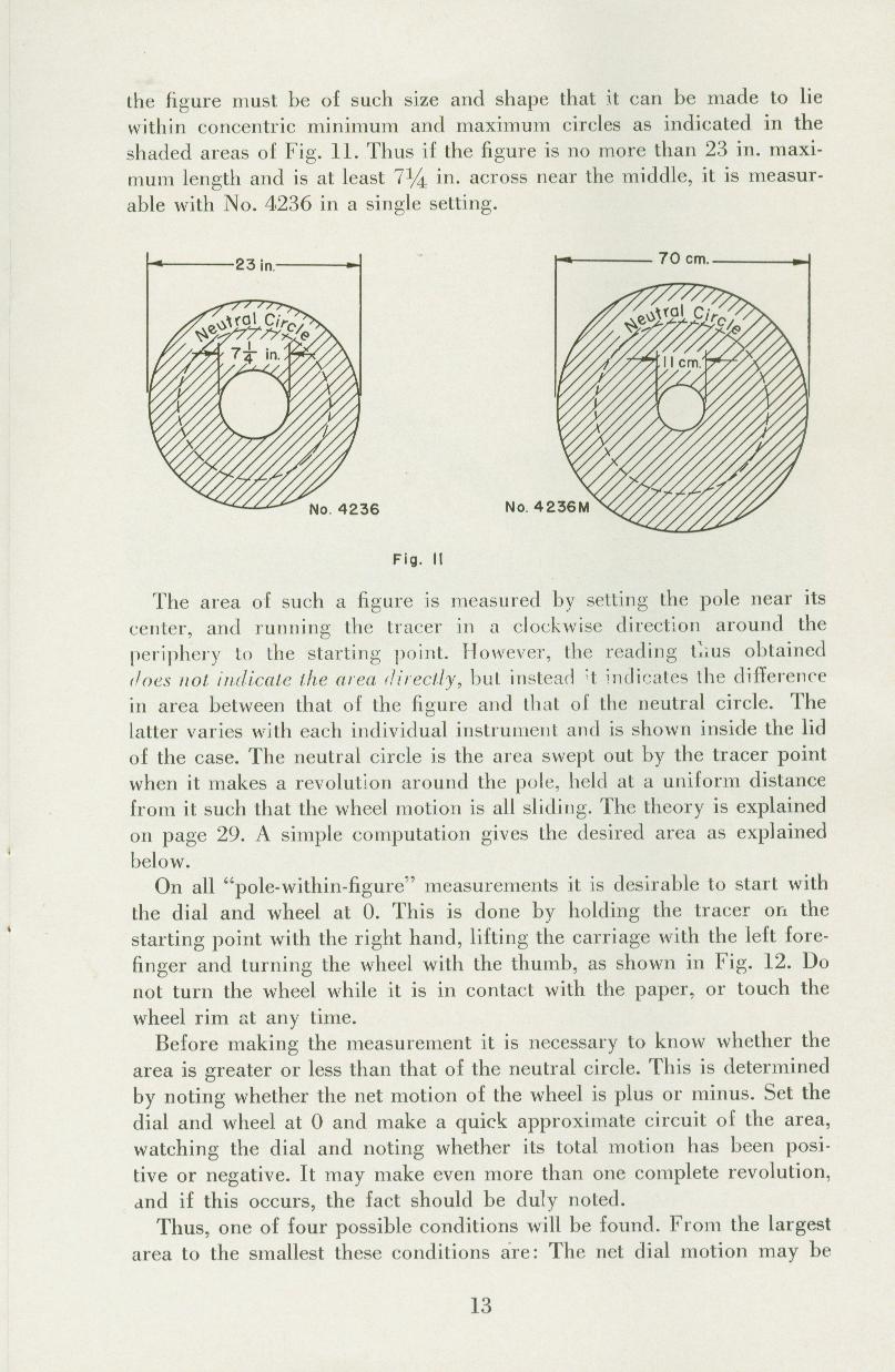
The added term is the area of the neutral circle, also called the zero circle or base circle: the circle the tracer point would draw if it went round the pole with the instrument set so that the wheel only slides, its axle pointing at the pole. Its radius R satisfies R² = l² + 2al + r², from the right angle at the wheel. So with the pole inside, the area measured is the neutral circle plus or minus what the wheel records, depending on whether the figure is larger or smaller than the neutral circle.
For the 4242 family K&E gives πD = 2.500 in and a = 1.151 in. The pole arm’s scale “does not indicate its true length”, so instead of calculating, K&E found for each instrument the pole arm setting that makes the neutral circle a round 200.00 sq in with the tracer arm set for square inches. On my card that setting is 30.82. Moving the pole arm index 2.94 further gives a neutral circle of 2,000.0 sq cm with the metric tracer setting: 33.76 for my instrument.
3.4 The same thing by Green’s theorem
Mathematicians prove it another way. The wheel’s net roll is the line integral, round the outline, of the component of the tracer’s motion perpendicular to the arm. Green’s theorem turns a line integral round a closed curve into an integral over the area inside it, and with the joint constrained to a circle round the pole and the arm of fixed length, the integrand comes out to exactly 1: the line integral is the area. R. W. Gatterdam’s “The planimeter as an example of Green’s theorem” (1981), Bill Casselman and John Eggers’s AMS feature column (2008), and Robert Foote’s planimeter pages at Wabash College set it out in full. Foote’s “moving segment” picture is perhaps the clearest: a segment moving over the plane sweeps area at the rate of its length times its sideways speed, which is exactly what the wheel measures.
3.5 What “compensating” cancels
A real instrument is not perfect. The most important flaw is a wheel whose axle is not exactly parallel to the tracer arm. John Eggers’s paper “A Closer Look at the Compensating Polar Planimeter” (College Mathematics Journal, 2020) shows what happens: with the axle tilted by a small angle ϑ, the reading picks up two errors. One, a factor of sec ϑ, is the same for every figure and can be calibrated away by adjusting the tracer arm with the testing rule. The other depends on the shape traced and cannot be calibrated away. But when the instrument is set up with the joint on the other side, the mirror image of the same error appears with the opposite sign, so averaging a reading with the pole on the left and one with the pole on the right cancels the misalignment error exactly. That is what the ball joint, Coradi’s 1894 improvement, was for, and why K&E’s manual tells the user to test both ways and average if one reads high and the other low.
3.6 Practical consequences
K&E’s manual draws some lessons from the theory (page 31):
- With the pole outside, results are independent of the pole arm length and the wheel position.
- A shorter tracer arm turns the wheel more for a given area, so it reads more finely but covers less ground; a longer one covers large areas less precisely. The limit of reading is always one vernier unit.
- Accuracy needs the wheel axle precisely parallel to the arm, bearings nearly frictionless and free of play, a light wheel, a true rim of exactly known diameter, a rim surface that grips the paper, and uniform graduations.
- The arms should meet at an angle between about 15° and 165°, better 30° to 150°: near the extremes the wheel turns very fast and small errors grow.
Further reading
- K&E, Compensating Polar Planimeters, chapter VI.
- J. Y. Wheatley, The Polar Planimeter (1903), chapters II–III, the “zero circle”.
- J. Eggers, “A Closer Look at the Compensating Polar Planimeter” (2020).
- H. J. Frost, “A Treatise on Planimeters” (2025).
- R. L. Foote, “How planimeters work”, persweb.wabash.edu/facstaff/footer/Planimeter.
- O. Bryant and C. Sangwin, How Round Is Your Circle? (Princeton, 2008), chapter 8.
Comments (0)