VFD Calculators · Volume 5
Inside the Machines
The makers of VFD calculators published almost nothing about how they worked. Service manuals existed, for dealers, and a few survive in collections, but none of those for the fluorescent machines is known to be online. What is online is better for understanding them: Brent Hilpert’s schematics, redrawn by hand from working machines on his Early Electronic Calculators pages, with the voltages, clock rates and scan rates he measured. This volume walks through seven of them, from a discrete-logic desk machine of 1971 to single-chip pocket and desk calculators of the late 1970s, and then looks at the chips themselves.
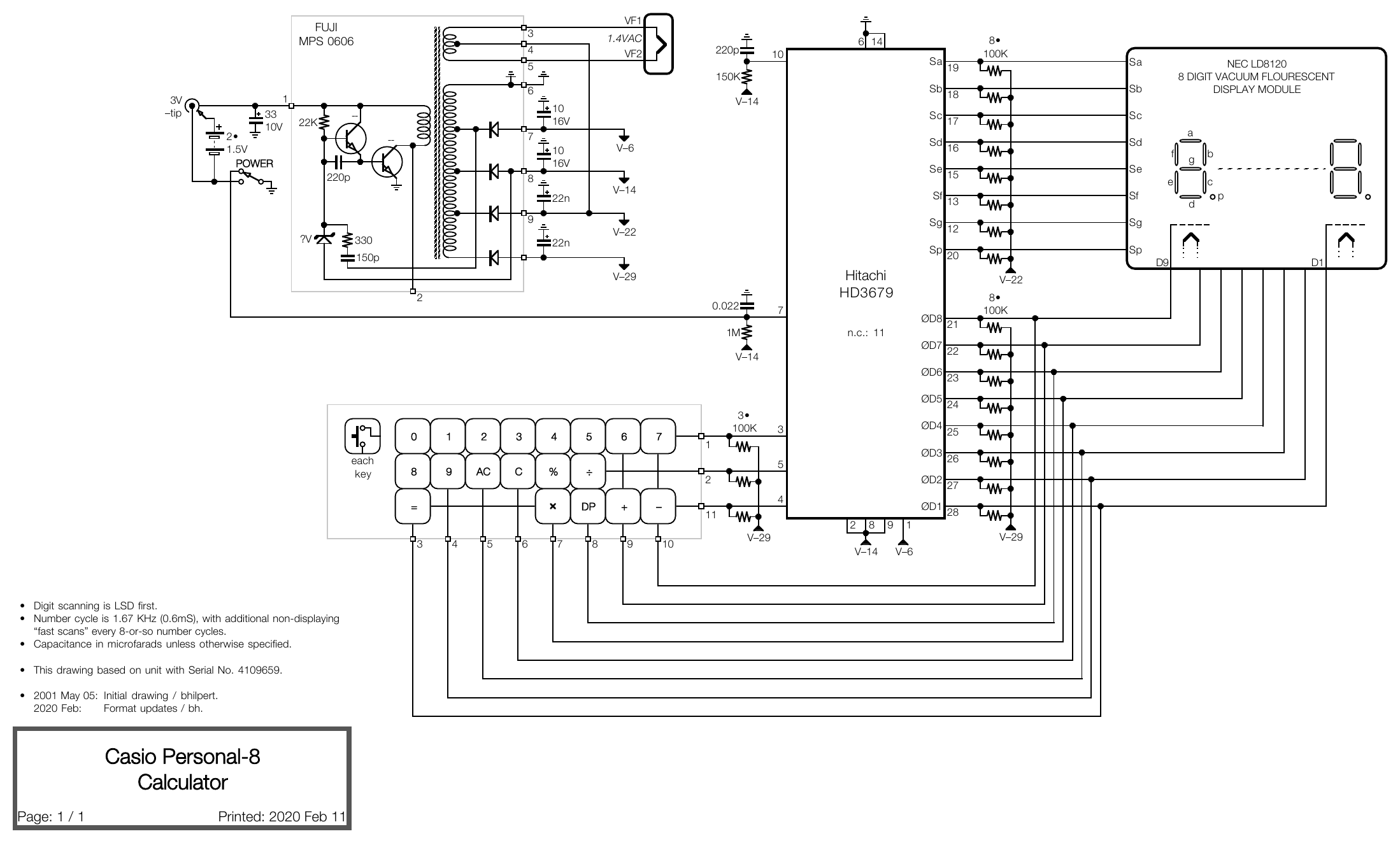
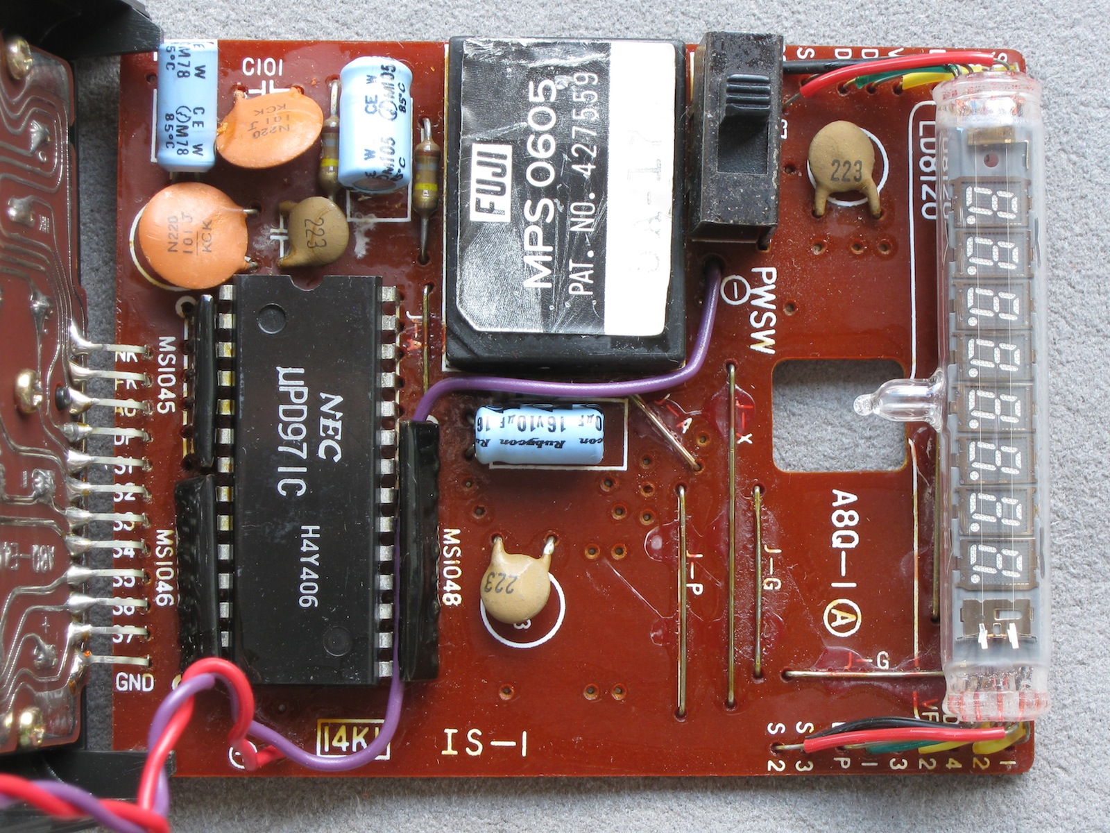
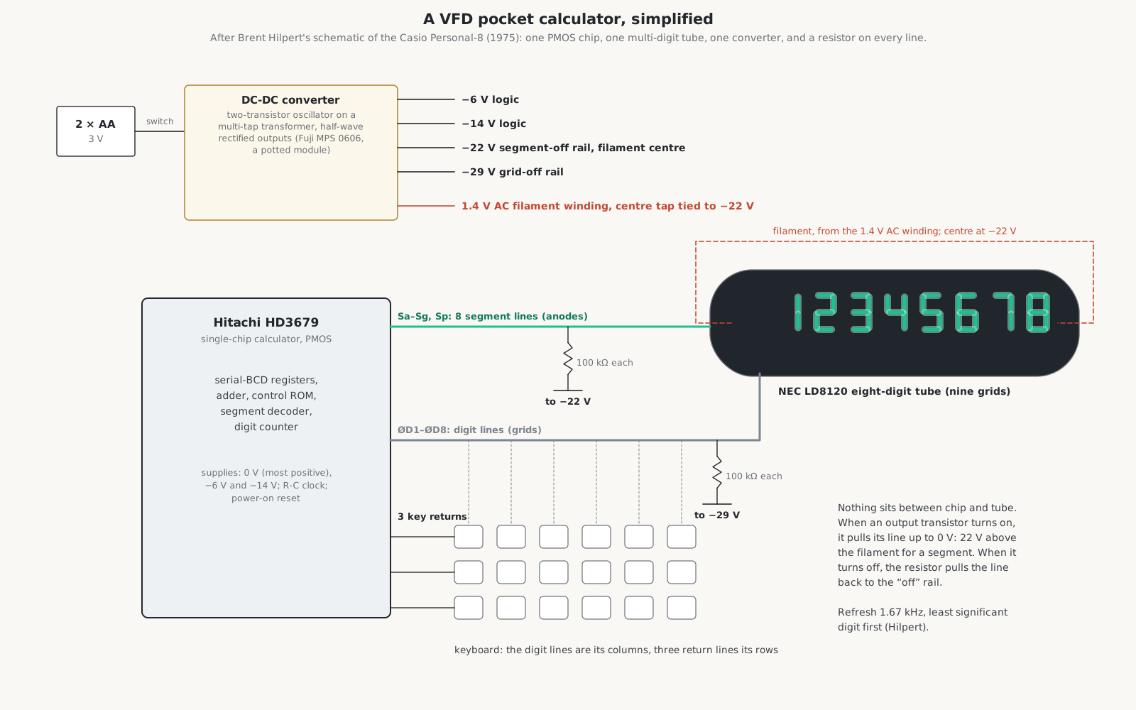
5.1 A pocket machine: the Casio Personal-8 (1975)
The Personal-8 is the whole idea in its simplest form: one chip, one tube, one converter, a keyboard, and a resistor on every line.
- Power. Two AA cells, 3 V. A Fuji MPS 0606 potted module holds a two-transistor oscillator on a multi-tap transformer. Its secondaries are half-wave rectified into −6 V and −14 V for the chip, −22 V and −29 V for the display, and a 1.4 V AC winding feeds the filament, its centre tap tied to the −22 V rail.
- Chip. A Hitachi HD3679 single-chip calculator in PMOS, with an R-C clock (220 pF and 150 kΩ) and a power-on reset (0.022 µF and 1 MΩ).
- Display. An NEC LD8120 eight-digit tube with nine grids. Eight segment outputs, Sa to Sg and the point Sp, go straight to the tube’s segment pins, each with a 100 kΩ resistor to −22 V, the filament potential. Eight digit outputs, ØD1 to ØD8, go straight to the grids, each with 100 kΩ to −29 V, seven volts below the filament.
- Keyboard. Twenty-four keys in three rows. The columns are the same digit lines that drive the grids; the three rows are the chip’s three key returns, each pulled down by 100 kΩ to −29 V.
- Timing. The digits are scanned least significant first, and the whole row is refreshed 1,670 times a second, with extra “fast scans” that light nothing every eight or so cycles.
5.2 A desk machine with no drivers: the CDK C1HB (1977)
The C1HB is the same idea on the desk. Its chip is a Texas Instruments TMS1273, one of TI’s high-voltage TMS1000-family microcomputers, with outputs rated to 35 V. Nine segment lines and thirteen digit lines run from the chip pins straight to a twelve-digit Itron FG139A3 module with M and arrow symbols, each with a 100 kΩ resistor to −35 V. There is no transistor between chip and tube. The keyboard is two rows on two key returns, and the switches are read on a third through diodes. A 117 V transformer gives −7 V to a two-transistor blocking oscillator, which makes −15 V for the chip, −35 V for the display and the filament supply.
5.3 Discrete drivers and a DC filament: the Victor Medalist 204 (1976)
The Victor 204 has one chip, a Rockwell A4540CB, whose outputs cannot take the display voltage. So every segment line (Sa to Sg, the point and a symbol line) and every digit line (ØD1 to ØD13) has its own PNP transistor, emitter to ground, collector pulled down to −55 V through 47 kΩ. The tube is a Futaba 13-MT-26 module with twelve digits and a symbol position, on a 27-pin connector. Its filament takes 4.6 V DC at 60 mA, rectified from a transformer winding, with the positive end held at −40 V. The display is refreshed only 136 times a second, most significant digit first, the slowest scan in this series and still free of flicker. The chip also reads a rotary decimal-point selector through the keyboard lines.
5.4 Transistor arrays: the Olympia CD401A (1974) and Sharp ELSI-804 (c. 1973)
The Olympia CD401A, made in Japan for Olympia Werke, has two Texas Instruments chips: a TMS0206 calculator and a TMS0318 that generates fourteen digit strobes. The calculator chip puts each digit out in BCD on four lines; a Hitachi HD3281P decodes it to seven segments; Toshiba TM4312 inverters and TM4352 PNP arrays switch the segments of a Futaba 13-MR-01 tube, with 150 kΩ to −55 V. The digit strobes go through more TM4352s to the grids. A converter runs from a rectified 7.7 V mains winding, and the filament takes 1.6 V DC with its supply tied to the −47 V line. The clock is 136 kHz and the display is refreshed 566 times a second.
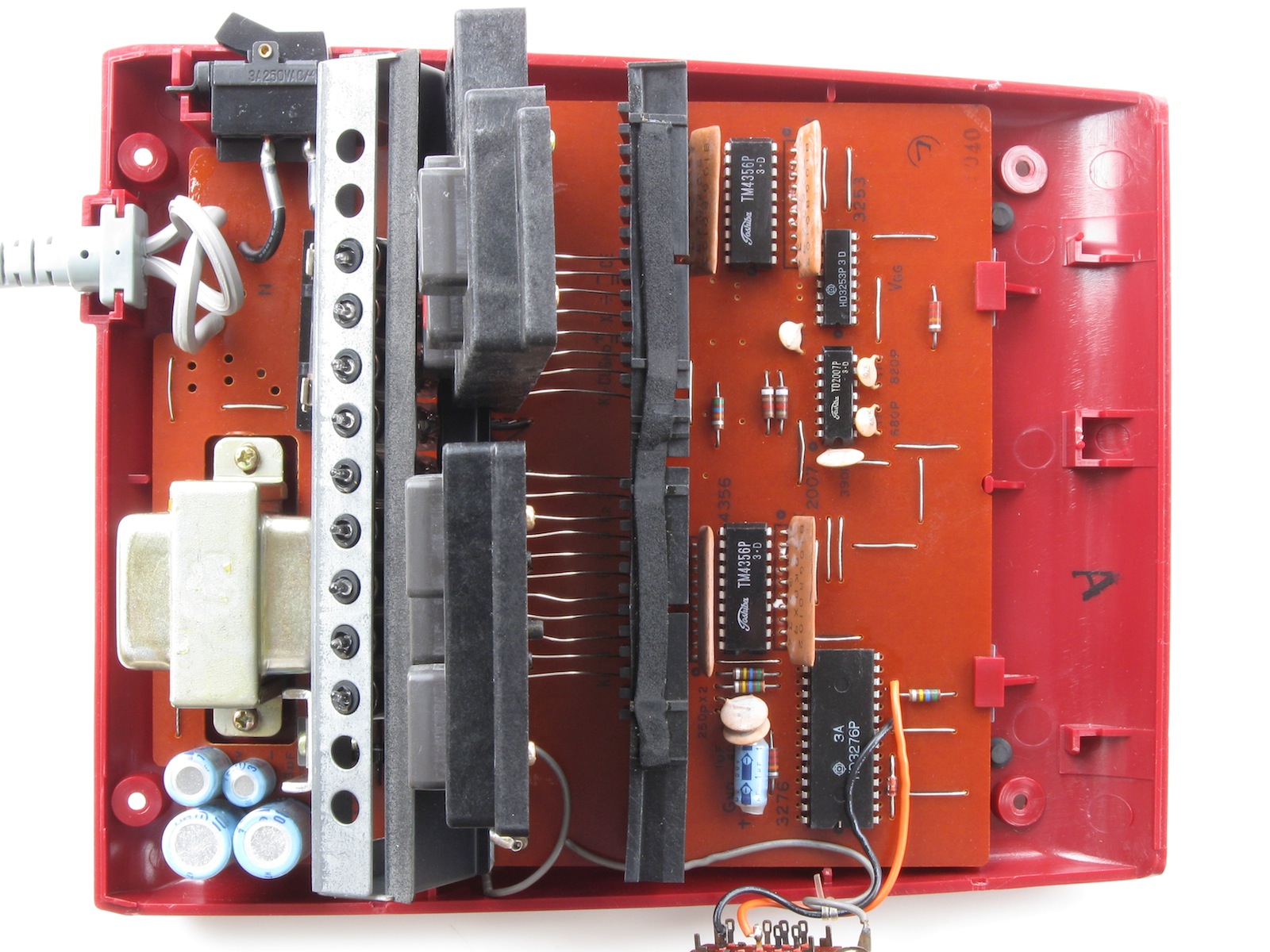
The Sharp ELSI-804 uses nine single-digit tubes, Futaba DG10Q1 or NEC LD8051, with a Hitachi HD3276 calculator chip and a Toshiba TD2007 clock running at 46.1 kHz. A Hitachi HD3253 decodes the segments, and Toshiba TM4356 arrays drive segments and grids, with 50 kΩ pull-downs to −44 V and −49 V. The filaments of all nine tubes are in series through 130 Ω from one transformer winding, returned to −44 V. As the display volume showed, one digit on the display lasts exactly one digit time of the arithmetic.
5.5 Three chips and discrete PNPs: the Miida MC800 (1971)
The Miida MC800 is built on Omron’s three-chip ALPHA set: ALPHA1 handles the keyboard and control and gives the sign outputs, ALPHA2 the segment outputs, ALPHA3 the digit outputs. Discrete A628A PNP transistors, emitters at −2 V, drive eight NEC LD8027 single-digit tubes with 100 kΩ (segments) and 10 kΩ (digits) to −58 V. Each digit is lit for three clock periods and blanked for the fourth, and leading zeros are suppressed by withholding their grid pulses. The minus sign and the overflow mark are two tiny incandescent lamps.
5.6 Before the single chip: the Royal Digital I (1971)
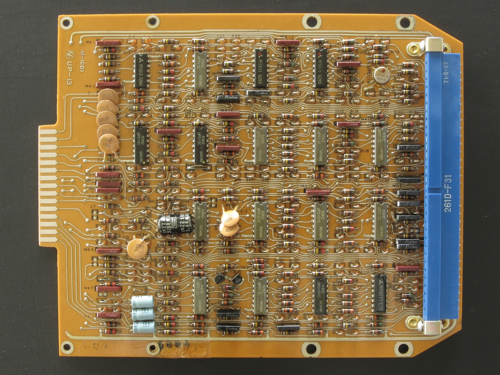
The TEAL Royal Digital I, Hilpert’s eighteen-page schematic shows, is a machine of the transition: 29 chips, NEC µPD-series and Mitsubishi M58-series MOS logic running on −24 V, and ten Ise DG-12C single-digit tubes, the type whose 1968 datasheet gives the ratings in the tube volume. Its filaments are wired in series, a zig-zag through all ten tubes, with the centre of the string returned to −77 V through 620 Ω. Its grid drivers share a common transistor, kicked by a short pulse at each digit boundary, that turns every grid off for a moment between digits: the blanking described in the display volume, done with one part. Special logic after the segment decoder gives the right-most digit a half-height zero. Hilpert’s theory of operation for this machine is listed on his site but was not available when this series was written.
5.7 A charge pump: the TI-1025 (1979)
Texas Instruments’ TI-1025 runs from a 9 V battery and uses a capacitor charge pump at 61.4 kHz, rather than a transformer, to make −22 V and −9 V. Its filament is fed with a square wave of about 7 V at 30 per cent duty and 1.5 kHz, an AC supply made without a winding. The tube is an Itron FG85C1 eight-digit module, driven by a TI TMC0923 chip and refreshed about 190 times a second.
5.8 The first handhelds: the Sharp EL-8 (1971)
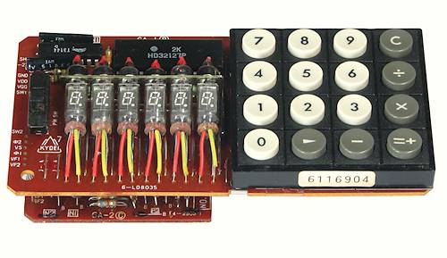
The EL-8 used the four MOS chips of the QT-8D desk machine, each with a job: the NRD2256 for timing, keyboard input and display generation; the AC2261 for control; the DC2266 for the decimal point; the AU2271 for the arithmetic and the registers. A CG1121 bipolar clock in a TO-5 can made the two-phase clock of about 45 kHz from a 90 kHz master. The chips could not drive the tubes, so six Hitachi HD3120 and three HD3121 driver packages sat between them and eight Itron DG10L tubes and an SP8A sign tube. The whole thing ran on −25 V from a 12.5 kHz inverter. The keys are glass reed switches worked by magnets.
5.9 The calculator chip
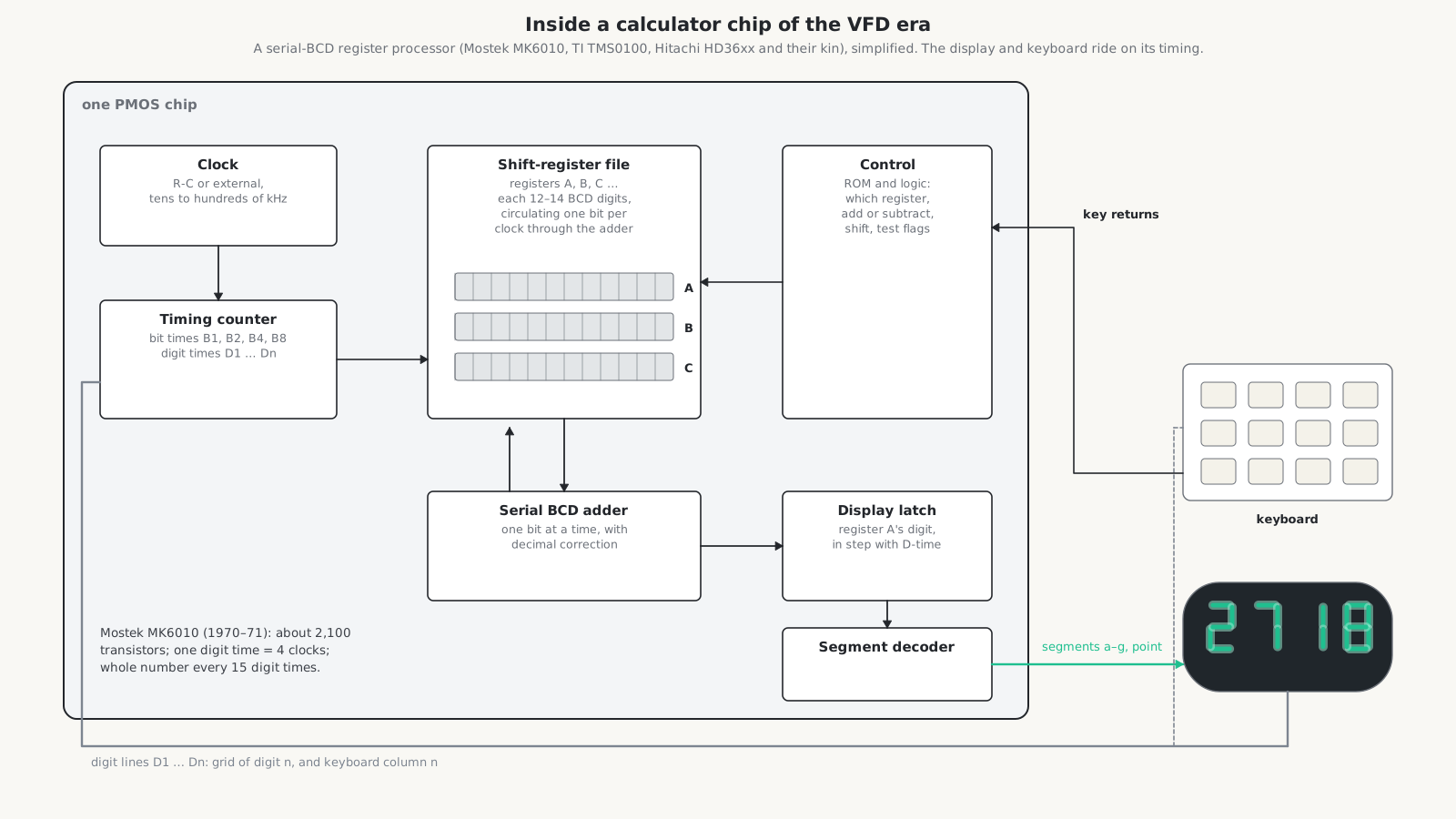
The chips behind these machines share an architecture, whoever made them. Numbers are held as binary-coded decimal in shift registers, each 12 to 14 digits long, that circulate continuously. The arithmetic is done one bit at a time by a serial adder with decimal correction as the bits stream past. A timing counter divides the clock into bit times and digit times. Joerg Woerner’s notes on the Mostek MK5013 put it in two lines: one digit time is four clock cycles, for the bit-serial adder, and one scan cycle is always fifteen digit times, twelve digits, the sign and housekeeping.
- Mostek MK6010 (1970–71), for Busicom: about 2,100 transistors, shift-register memory for two twelve-digit numbers. Woerner notes that the MK6010 was a 25-volt process for desk machines and the MK6010L a 15-volt one for handhelds.
- Texas Instruments TMS1802, announced on 17 September 1971 and renamed TMS0102: 3,520 bits of ROM (320 words of 11 bits), a 182-bit serial memory holding three thirteen-digit registers, and a decimal arithmetic unit. It had no display drivers; LED machines added separate segment and digit driver chips. Its 28 pins are a clock, eleven digit lines, eight segment lines and a point, three key returns, and the supplies.
- TMS0800 and TMS1000 (from about 1974): microcontroller-like chips. Ken Shirriff’s simulator of the TMS0800 shows 11-digit BCD registers, 11-bit instructions, a 320-word ROM and about 4,000 instructions a second, with a SYNC instruction that ties the program to the display scan. The TMS1000 family’s high-voltage TMS1070 and TMS1270 drove fluorescent displays directly.
- Rockwell: the four-chip Sharp set of 1969–71, then single chips such as the A4540 in the Victor 204 and the PPS-4 microprocessor in Sharp’s programmable PC-1001.
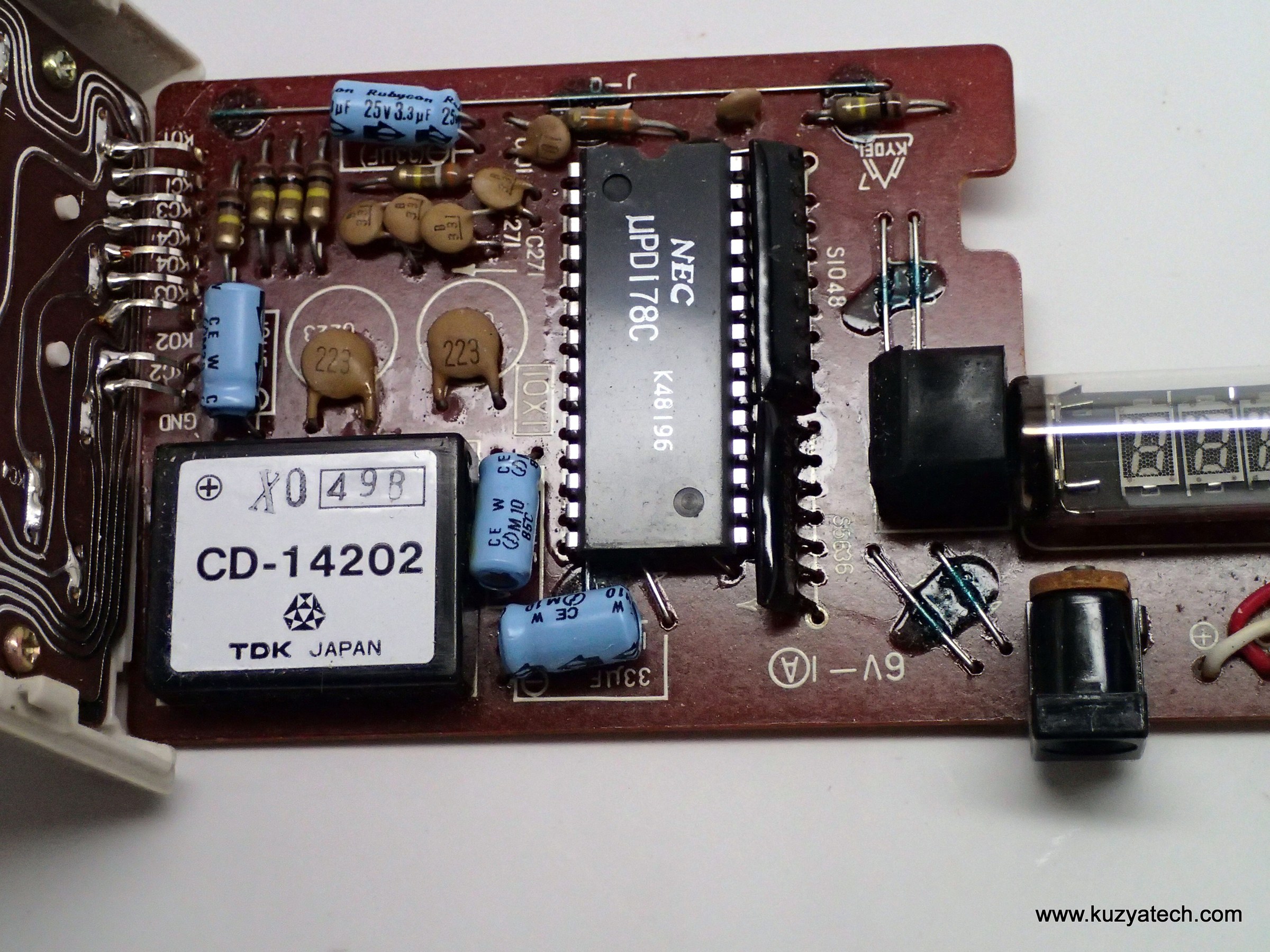
- Hitachi: the HD3276, HD3679, HD32127 and their many relatives.
- NEC: the µPD-series chips in Casio’s pocket machines.
The display sits on this structure almost for free. The digit counter that steps the arithmetic through the register also chooses which grid is up, and the digit of register A passing through the adder at that moment is latched, decoded and put on the segment lines. The keyboard is read on the same digit times. A calculator chip of this kind needs only a clock, its supplies, a segment line for each segment, a digit line for each digit, and a few key returns, which is why a whole pocket calculator could be one 28-pin chip, one tube and a converter.
5.10 The schematics in the Library
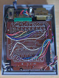
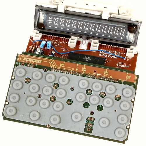
All of Hilpert’s VFD schematics used here are in the Library: the Casio Personal-8, CDK C1HB, Victor Medalist 204, Olympia CD401A, Sharp ELSI-804, Miida MC800, Royal Digital I and TI-1025, with the Miida MC840 and MC1214, Toshiba BC-0802, Facit 1114, Ricomac 1216, IME 41, Royal Digital V, Lloyd’s 55 and 310, AGS 14, Sharp EL-8131 and LogicData TA-9. The chip documents include the TI TMS 1000 Series Data Manual, the Mostek Integrated Circuit Guide of 1974, Rockwell’s MOS LSI building blocks for calculators of 1971, and the Sanyo ICC-0081 logic circuit diagram, a rare factory service document.
Comments (0)