Soviet Calculators · Volume 8
Repair and Restoration
Soviet calculators were built to be repaired: they came with circuit diagrams, measured voltages and a fault-finding order in the manual, and their manuals listed the warranty repair workshops. Forty years on, the common faults are few and well known, and most can be put right with a soldering iron, a bench power supply and a couple of capacitors. The chips are another matter: the MK-61’s are bare dies under a blob of resin, and the only replacement is another board.
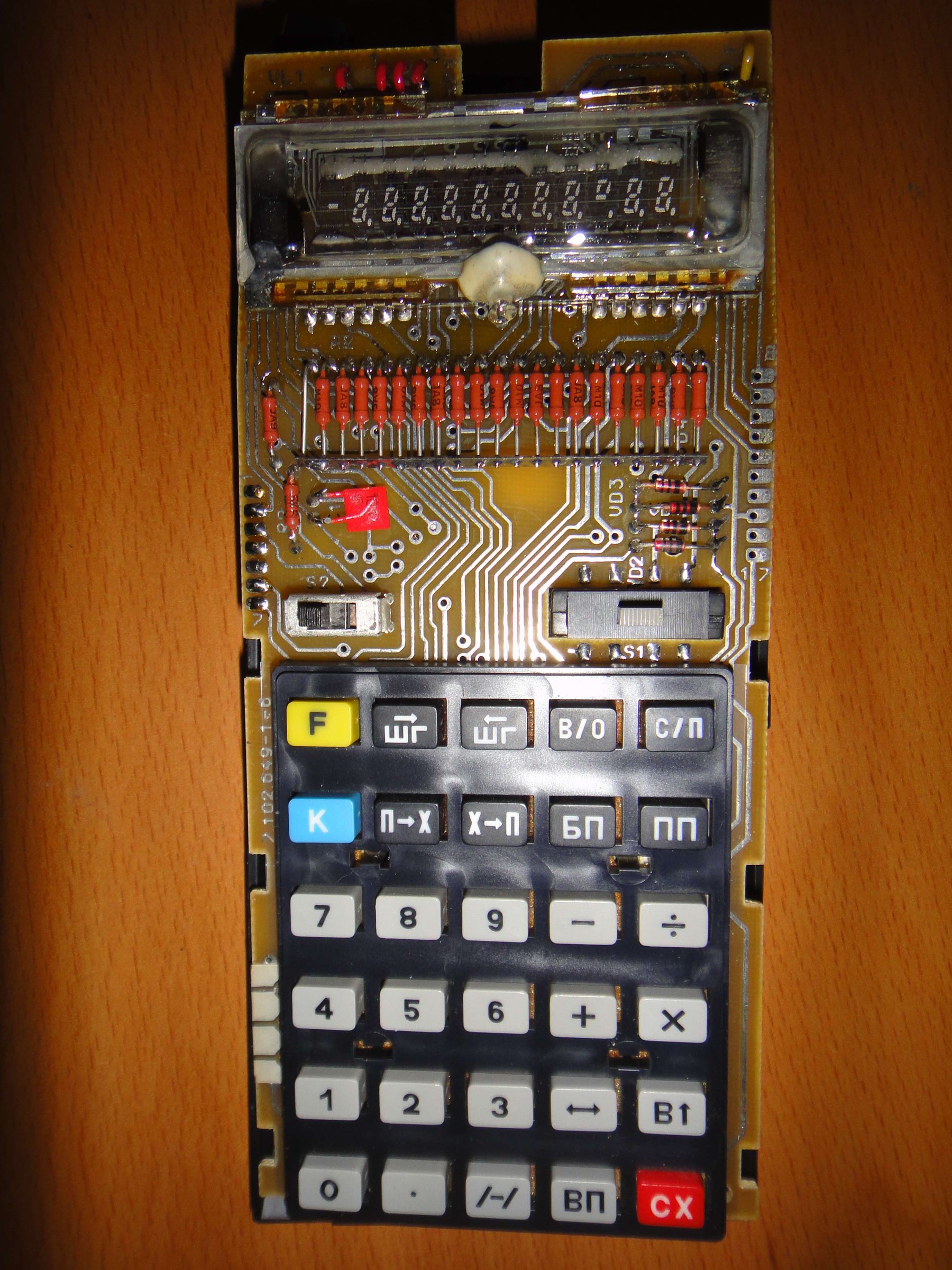
8.1 The MK-61’s power path, and where to look first
The figures are from the MK-61 manual and José Mesquita’s notes to his translation of it:
- Supply: three A-316 cells (AA size; alkaline cells are fine), 4.5 V, or the Д2-10М adapter. Battery positive is ground.
- Converter outputs, at its pins: pin 9 is battery positive and ground, pin 3 battery negative, pin 4 −15 V for the logic, pin 7 −27 V for the display, and pins 1 and 2 about 2.4 V AC for the filament.
- Current: about 100 mA with one digit lit and 130 mA with all twelve. “If the value is outside this threshold, investigate the DC-DC converter.”
- Electrolytics: “Defective electrolytic capacitors are a common cause for erratic or total operation failure.”
Mesquita’s order of search follows from that: leaking cells or corroded contacts first; then the power wiring and the switch; then the supply current; then the converter’s output voltages; then the electrolytic capacitors.
8.2 The faults that turn up
Table 1 — The faults that turn up
| Symptom | Cause | Notes |
|---|---|---|
| Dead on batteries; nothing drawn | corroded or loose contacts; the shorting contact in the adapter jack, which completes the battery circuit when no plug is in | clean or bend the jack contact |
| Comes on only sometimes; a few zeros; flicker | the ПД9-2 power switch not making contact | the commonest MK-61 fault; see below |
| Erratic display, scrambled digits, blanking, total failure | the converter’s electrolytic capacitor dried out: C3, 20 µF, in the MK-61; C3, 5 µF, in the B3-34 | one owner cured a stuttering display by replacing a 50 V, 20 µF capacitor on the power board |
| Supply current outside 100–130 mA | the converter: the КТ814 switch, the regulating transistors, the transformer | measure the three outputs |
| Failed after use on the mains | the Д2-10М’s unregulated 8.5 V open-circuit output, applied by plugging it into the mains first | follow the manual’s order of connection |
| Weak or uneven display | low drive to the tube; on the B3-34 the factory remedy is to fit VD4 the other way round | see the inside volume |
| Digits dim or missing, changing when the tube is pressed | cracked solder joints on the tube’s legs, or a failed contact inside the tube | resolder the legs; in one case a solder bridge across two legs was the fault |
| One digit and the minus sign dead | possibly the output driver inside the ИК1302, which drives the grids directly, rather than the tube | test by feeding the grid from a working line |
| All the decimal points lit | low cells, the manual’s own warning | |
| Keys bounce or wobble | the foam behind the keys gone sticky or crumbled; the contacts are bare pads without solder mask, and oxidise | replace the foam; clean the pads |
| Cracked tube | the vacuum is gone | replace the tube |
The manual itself warns: “Do not leave dead batteries in the MK … electrolyte leaking – the MK cannot be repaired.”
8.3 Replacing the power switch
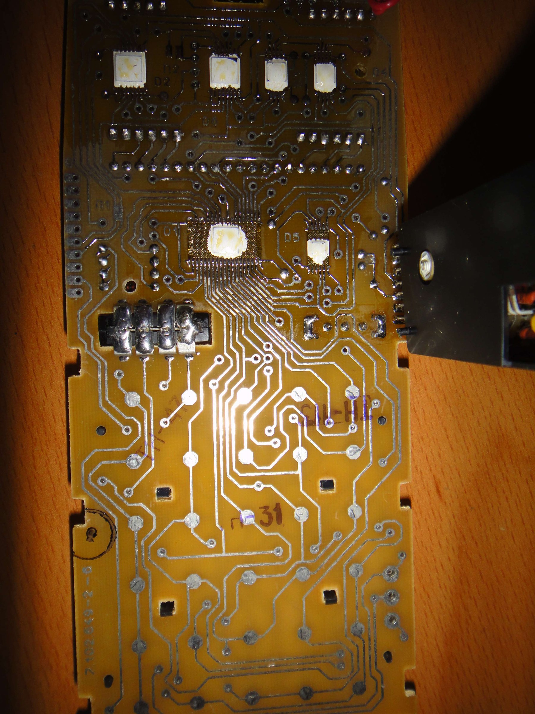
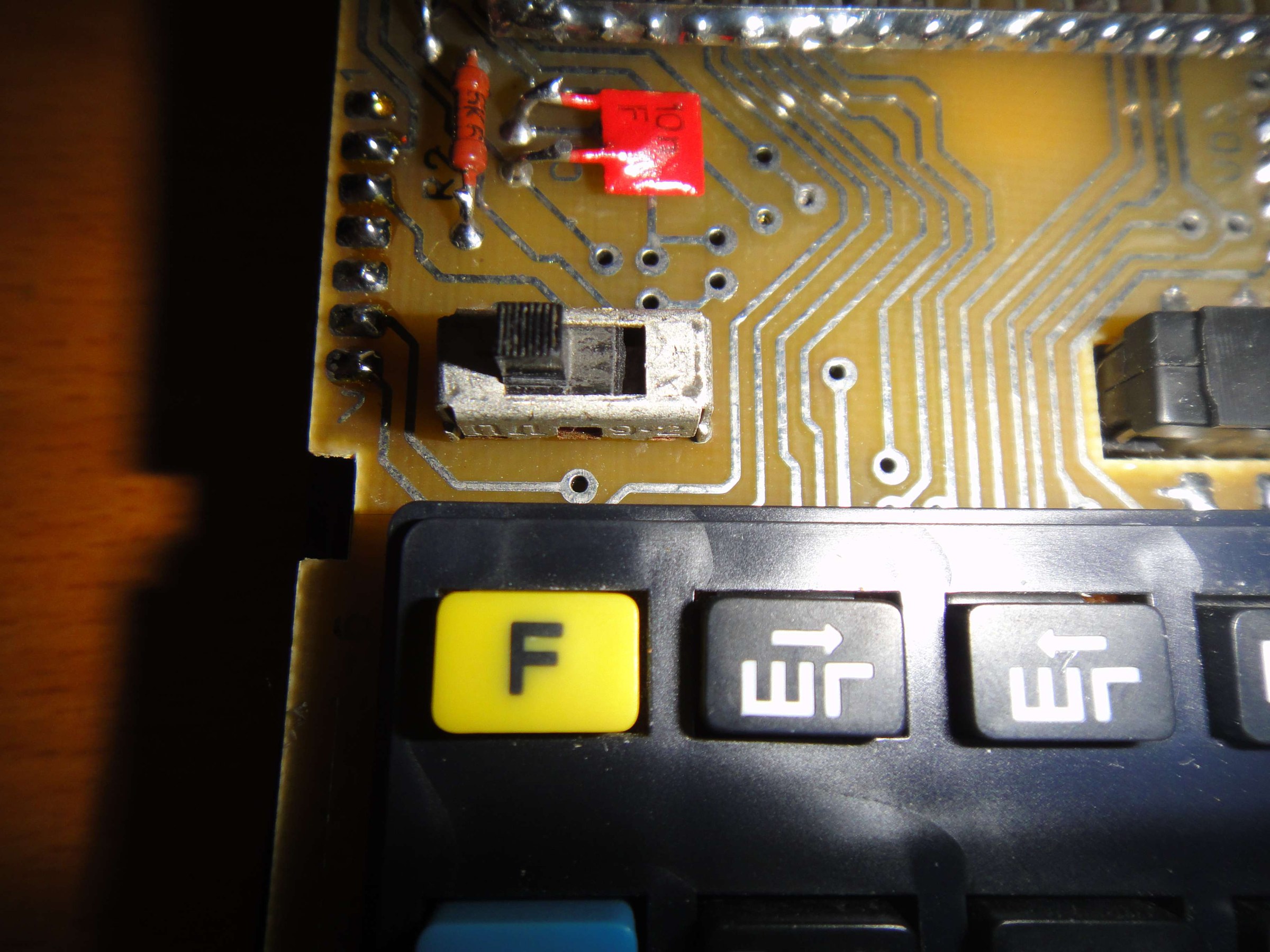
The MK-61’s slide switch, a ПД9-2, is its best-known weak point. One repairer’s account describes a calculator that “stopped turning on … occasionally … showed a few zeros or flickered”: a continuity test showed that the switch’s ON position no longer made contact. To get at it:
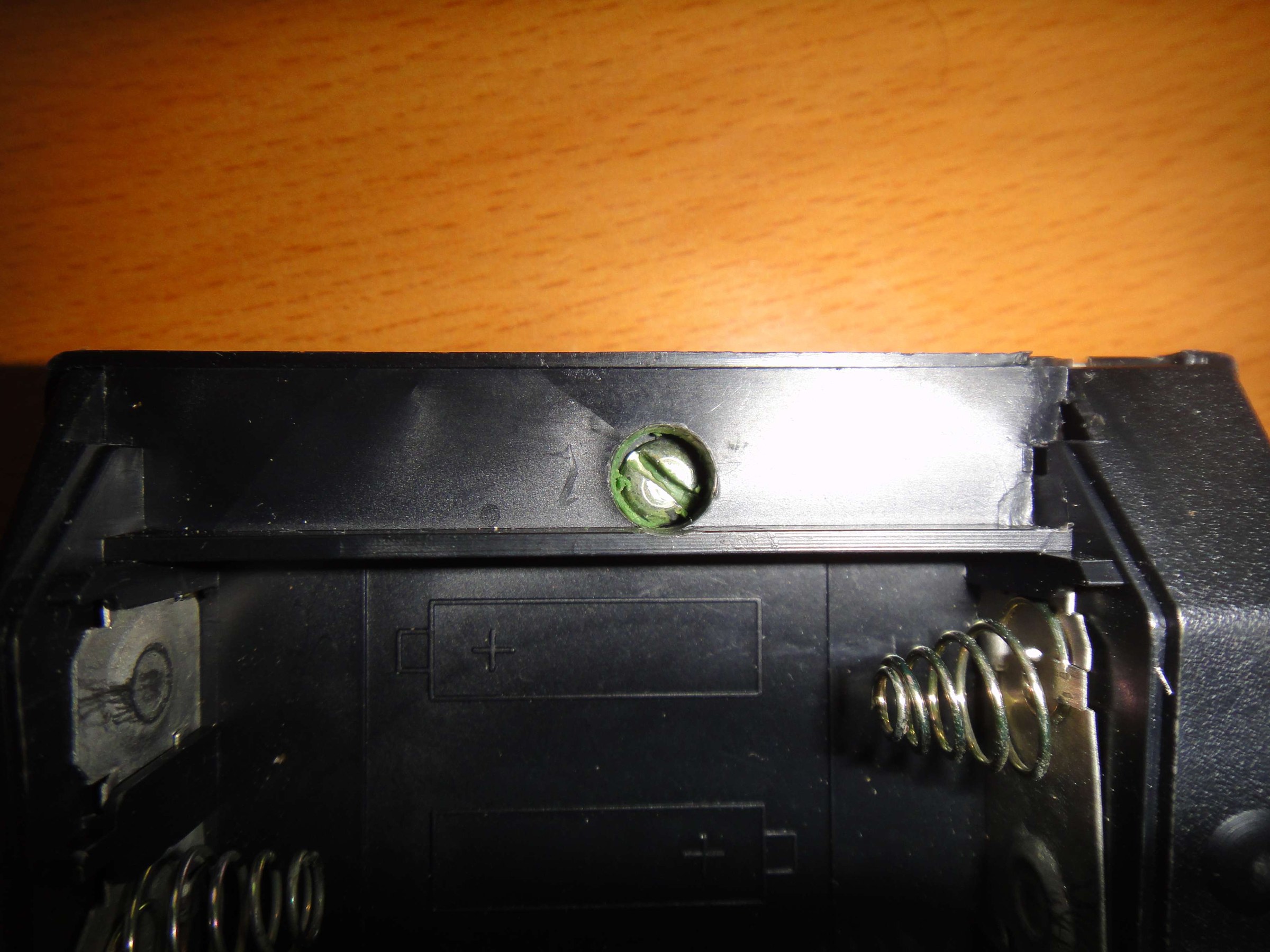
- Remove the battery cover. One case screw is sealed with wax, the factory’s warranty seal.
- Undo the screw, unsnap the case, and release the circuit board from six plastic clips.
- The switch’s metal shield acts as a heat sink and makes it hard to desolder; the repairer cut the shield away.
- Fit a new switch. New old stock ПД9-2 switches are sold by Ukrainian sellers, sometimes as “military switch PD-9-2”, in lots of twenty; the first replacement in that account was faulty too, so buy more than one.
8.4 Capacitors
The converter’s electrolytic is the part most likely to have failed after decades in a drawer. Hewlett-Packard Museum forum members who restore MK-52s and MK-61s say it is the first thing to replace after long storage, advise the same capacitance at a higher voltage rating, and warn that “good solder and unsolder skills are required in order to not destroy the pcb copper traces”: the copper on these boards is thin and lifts easily. A Habr commenter puts it more bluntly of the MK-52’s capacitors: “they all dry out”.
8.5 A safe first power-up
For a machine that has not been switched on for years:
- Remove the cells and clean any corrosion.
- Power it from a bench supply at 4.5 V for an MK-61 (4.8 V for a B3-34’s four NiCd cells), connected to the battery contacts, with the current limited to about 150 mA. Never use a bare Д2-10М for a first test.
- Switch on and read the current. About 100 to 130 mA is healthy; much more means a short, much less a dead converter.
- Measure −15 V, −27 V and the 2.4 V AC filament supply at the converter before suspecting the chips.
- Wait at least 30 seconds between switching off and on again, as the manual says.
- Run the circle-area program from the operating volume as a test.
8.6 Spare parts
- Display tubes. Replacement ILC2-12/8L tubes for the MK-61 and MK-52 have been sold on eBay for one to three dollars each, as “ILC2-12/8L VFD Display Nixie Tube for Calculators Electronika MK-52 MK-61”; they are said to be easy to find.
- Switches. ПД9-2 new old stock from Ukraine.
- Adapters. The Д2-10М for the MK-61, B3-36 and B3-23; the Д2-37А for the MK-52; the Д2-10К for the MK-85; the БП2-3 for the B3-34. Because the Д2-10М is unregulated, a modern regulated 5 V supply with the right plug and polarity is a safer substitute.
- Cells. MK-61: three AA. MK-52: four AA. B3-36: four Д-0,25 NiCd buttons by one source, three by another. B3-35: three A-316. B3-26: four AA. B3-30: two Д-0,06. MK-85: four SC-0.18. The MK-61’s manual forbids rechargeable cells, though period sources describe NKGTs-0,45 NiCd cells of the same size being used in it, with three times the capacity.
- Chips. There are none to buy. A dead К745 die means a donor board, or one of the modern emulator boards described in the collecting volume.
8.7 Documents
The circuit diagrams in the Library are the best guide to any repair: the MK-61, the B3-34, the MK-52, the B3-18A, the B3-14, the B3-26, the MK-85, and the schematic printed in the MK-51 manual. Mesquita’s English MK-61 manual includes his hardware notes and test checklist.
Comments (0)