Nixie Calculators · Volume 8
Building One Today
Original Nixie calculators are rare, heavy and fragile, but a new one is well within reach of anyone who can solder. Nixie tubes are still easy to buy: the Soviet factories made them in huge numbers into the 1980s, and new old stock is sold today. High-voltage supplies come as ready-made modules the size of a postage stamp. A microcontroller costing a few dollars can do the arithmetic that took the ANITA 177 gas tubes. This volume looks at what others have built, what a build needs, and how the circuits of the original machines translate to modern parts.
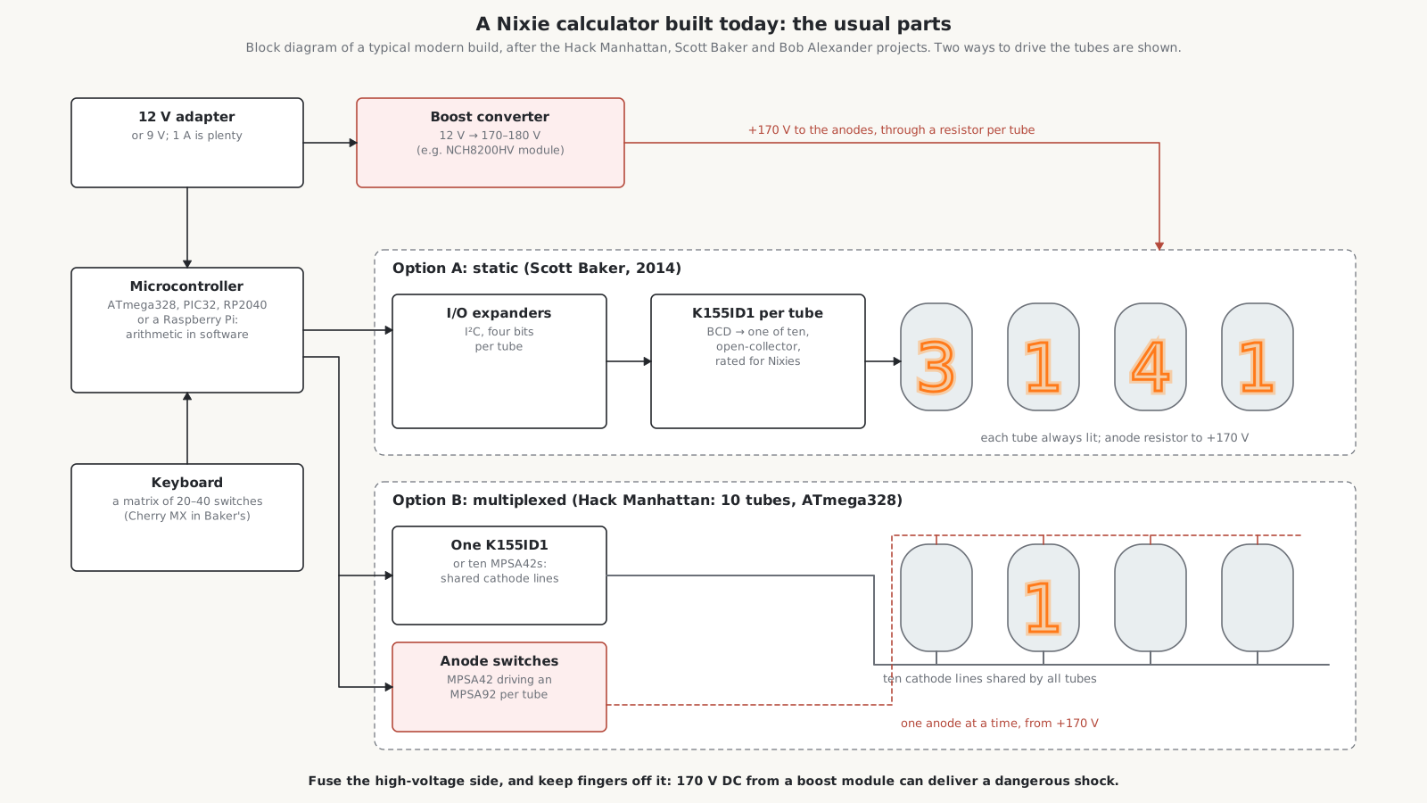
8.1 Projects others have built
Bob Alexander’s Modern Electronic Package for the Wang 300. The Wang 300’s keyboards are fairly common, but the electronic packages that did the arithmetic are rare, expensive and “frequently broken”: discrete DTL, three voltage levels and core memory, hard to repair. In 2019 Bob Alexander designed a single circuit board, built around a PIC32 microcontroller, that fits inside a 300, 310, 320 or 360 keyboard console and makes it a working calculator on its own. It has level shifting for the console’s signals, its own Nixie high-voltage supply, and software that closely emulates the original Wang’s logarithmic multiplication and division, including its flashing decimal point on overflow. The only difference its author knows of is that multiplying a large number by zero gives .0000000000 rather than the original’s 000.0000000. It also adds a Reverse Polish calculator mode, a keyboard test, and a clock set by GPS that cycles every digit at midnight to prevent cathode poisoning. A second version of 2024 is an external box on a cable, like the original package, with a real-time clock. The manual is in the Library. It is the nearest thing to a reproduction of a Nixie calculator anyone has made: original keyboard and tubes, modern arithmetic.
Scott Baker’s Raspberry Pi Nixie calculator (2014). Eight Soviet IN-12 tubes, bought used at a dollar or two each, on two four-digit boards; a K155ID1 decoder-driver for every tube, so the display is static; I²C expander chips to feed the decoders; a TL494 boost converter for the high voltage, run from a 12 V, 1 A wall adapter; 40 Cherry MX Blue key switches; and a Raspberry Pi doing the arithmetic. Baker later offered it as kits and assembled units through Kickstarter.
The Hack Manhattan Nixie calculator. Ten tubes, multiplexed, driven by an ATmega328 microcontroller, with a boost converter from 9 V to 180 V. Its builders’ lessons are worth repeating: they swapped the base and emitter leads of their high-voltage PNP transistors, miscalculated a resistor, and concluded that a 180 V supply needs fuses. The design files are on GitHub.
No current Tindie kit for a Nixie calculator was found; the Nixie kits on sale are clocks. Search results for “best Nixie calculator kits” are mostly spam.
8.2 What a build needs
Tubes. The Soviet IN-12 (a top-view tube) and the side-view IN-14, IN-16 and IN-17 are the usual choices: cheap, plentiful, and documented in datasheets that the Library holds in Dieter Wächter’s compilation. The IN-12 is usually run from about 170–200 V at 2–3.5 mA. Burroughs, Philips and Japanese calculator tubes are scarcer and better kept for restoring original machines. Buy one or two spares, matched in type.
High voltage. A boost-converter module from 9–12 V to 170 V costs about $12–17. The NCH8200HV, successor to the popular NCH6100HV, is typical; its designer warns that counterfeit copies are common and some are fire hazards. Alternatively, build a boost converter round a chip such as the TL494, as Baker did. Fuse it, and fit a bleed resistor across its output capacitor so that it discharges when switched off.
Drivers. Two approaches, both inherited from the 1960s:
- Static, with one decoder-driver per tube, as in the Wang LOCI-2: the K155ID1 is still sold and is the obvious part, a BCD to one-of-ten decoder with open-collector outputs that tolerate the Nixie’s cathode voltages. Simple to program and free of ghosts, at the cost of one chip and four signal lines per tube.
- Multiplexed, as in the Canon 163 and the later calculators: ten shared cathode lines, driven by one K155ID1 or by ten MPSA42 high-voltage NPN transistors, and an anode switch per tube, usually an MPSA92 high-voltage PNP turned on by a small NPN. Far fewer parts, but the software must time the strobing, blank between digits to prevent ghosts, and run the tubes at a higher peak current within their pulse ratings.
The display volume explains the pre-bias, the anode resistor and ghosting; the same rules apply. Work out the anode resistor from the supply, the tube’s maintaining voltage and the current: from 170 V, for a tube that maintains at 145 V and runs at 2.5 mA, (170 − 145) ÷ 2.5 mA = 10 kΩ; from 180 V, 14 kΩ.
Keyboard. Any matrix of key switches. Mechanical keyboard switches with printed keycaps are the easy route; salvaged keys from a dead calculator are the authentic one.
Brains. Any microcontroller. A calculator’s arithmetic is a few hundred lines of code. For authenticity, it can be written to work as the originals did, in binary-coded decimal, digit by digit, with the same rounding and overflow behaviour; Bob Alexander’s Wang emulation shows how far that can be taken. Wang’s logarithm method, in the theory volume, is a satisfying thing to implement: it needs nothing but shifts and additions and a table of seven constants.
Case. The originals were heavy: steel chassis, die-cast or thick plastic covers, the tubes behind a tinted window. A wooden or acrylic case with a red or orange filter in front of the tubes improves contrast greatly.
8.3 A rough budget
For an eight-digit calculator built from Soviet IN-12 tubes, as a rough estimate rather than a quotation:
Table 1 — For an eight-digit calculator built from Soviet IN-12 tubes, as a rough estimate rather than a quotation
| Item | Cost |
|---|---|
| Eight IN-12 tubes and sockets | $10–40 |
| 170 V boost module | $12–17 |
| Microcontroller board | $5–40 |
| Key switches and keycaps | $30–60 |
| Circuit boards | $20–40 |
| Drivers, resistors, connectors, fuse | $10–20 |
| Total | about $90–220, plus the case |
8.4 Safety
A 170 V boost converter feeding a Nixie display is a small power supply that can give a painful and potentially dangerous shock, especially across the hands. Fuse the low-voltage input, keep the high-voltage side covered, fit a bleed resistor, discharge the output capacitor before working on the board, and never work on it live with both hands. The Hack Manhattan builders’ conclusion, that a 180 V supply needs fuses, is a good one to start from.
8.5 A reproduction of an original?
Nobody appears to have reproduced an original Nixie calculator in the way the Curta has been reproduced, as in this site’s Giant Curta series. The closest are Bob Alexander’s Wang boards, which keep the original keyboard and display and replace only the electronics. A faithful reproduction of an ANITA, with real cold-cathode thyratrons and Dekatrons, would be a formidable project. A replica of the ANITA’s logic with modern parts, behind a row of twelve Nixies and a full Comptometer keyboard, is a more practical idea.
Comments (0)