Nixie Calculators · Volume 4
Driving the Display
A Nixie tube is simple to light on the bench: a supply of 170 volts or more, a resistor, and a wire to the cathode you want. Lighting twelve or sixteen of them from transistor or MOS logic that runs on 5 to 25 volts, changing the digits thousands of times a second, is a different matter. This volume describes how the calculator designers did it: the high-voltage supply, the anode resistor, the pre-bias trick that lets low-voltage transistors switch a high-voltage tube, the choice between static and multiplexed drive, and the details of decimal points, zero suppression and ghosting. Every Nixie calculator uses some version of these circuits, and they are where most display faults are found.
4.1 The supply and the series resistor
A Nixie must be fed from a voltage above its striking voltage, about 170 V, and its current must be set by something outside the tube, because once it glows the voltage across it stays at about 140 V whatever the current. The usual answer is a series resistor in the anode lead: the resistor takes up the difference between the supply and the tube’s maintaining voltage, and Ohm’s law sets the current.
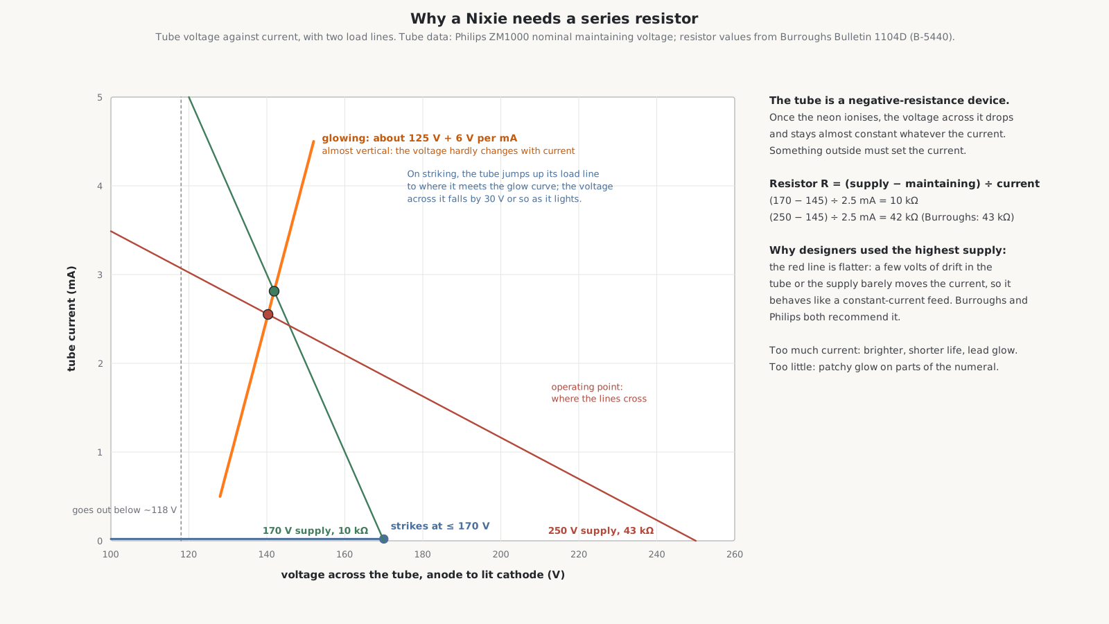
Burroughs’ Bulletin 1104D for the B-5440 tube gives the resistor as a table: 10 kΩ on a 170 V supply, rising to 43 kΩ at 250 V, chosen for 2.5 mA at the tube’s 145 V maintaining voltage. The arithmetic is simple: (250 − 145) V ÷ 2.5 mA = 42 kΩ. Both Burroughs and Philips recommended the highest supply available with the matching larger resistor, because it approximates a constant-current source: a few volts of variation in the tube or the supply then makes little difference to the current, and so to the brightness and the life of the tube.
The calculators followed the advice to differing degrees. The Wang 300 keyboards run their Nixies from +250 V. The Canon 163 has +200 V and +100 V display supplies; the Sharp Compet 20 uses +185 V; the Toshiba BC-1411 180 V; the Casio 121-B’s drivers have +180 V and +84 V pins; the SCM Cogito 414 has +200, +197 and +100 V rails. The ANITA Mk VIII is the outlier: its whole logic of gas tubes runs from about 495 V.
The supplies themselves are usually a winding on the mains transformer, a rectifier and a reservoir capacitor, unregulated or only roughly regulated, as on the Wang 300. Later machines raised the voltage electronically: the Friden EC-1115 makes its anode pulses of about 200 V with a charge pump from ±100 V rails, and the SCM 412 and 414 use a switch-mode supply. On the battery-powered Marchant I the Nixie voltage has to be generated from the 6 V of five AA cells.
4.2 The pre-bias trick
The first problem in driving a Nixie from transistors is the voltage. If the anode is at 170 V and an unlit cathode is simply left open, that cathode floats up towards the anode voltage; to switch it on, a transistor must pull it all the way down, and when off it must withstand nearly 170 V. Transistors that could do that were expensive in the early 1960s.
Burroughs’ answer, set out in its Catalogue 616 of about 1962, is the pre-bias. Each unlit cathode is held not at the anode voltage but at an intermediate voltage, typically 60 to 100 V, through a resistor or a diode to a bias rail. The lit cathode is pulled down to near 0 V by its transistor. The tube then sees:
- between the anode, at about 140 V above the lit cathode, and the lit cathode: 140 V, enough to keep it glowing;
- between the anode and each unlit cathode: only about 140 − 80 = 60 V, too little to glow.
The transistor itself only ever has to switch between 0 and the bias voltage, 80 V or so, never the full supply.
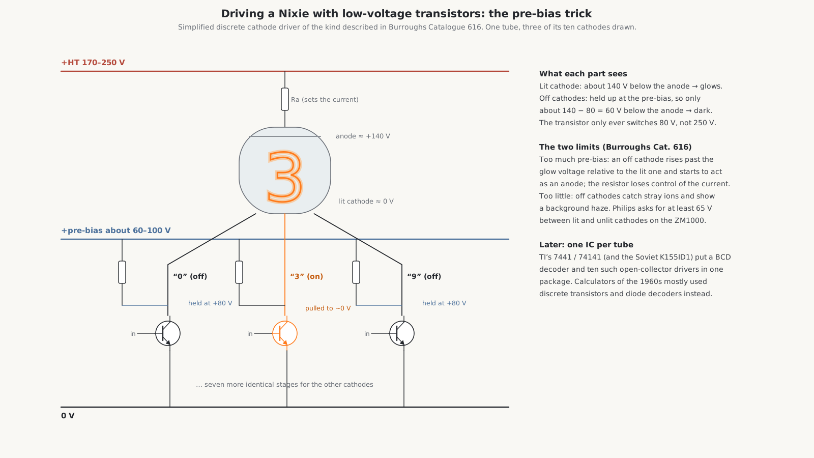
Catalogue 616 sets two limits on the bias. If it is too high, an unlit cathode rises above the glow voltage relative to the lit one and starts to behave as an anode, and the series resistor no longer controls the current. If it is too low, the unlit cathodes come close enough to the anode voltage to collect stray ions, and a faint background haze appears round the lit numeral. Philips specifies at least 65 V between lit and unlit cathodes for the ZM1000.
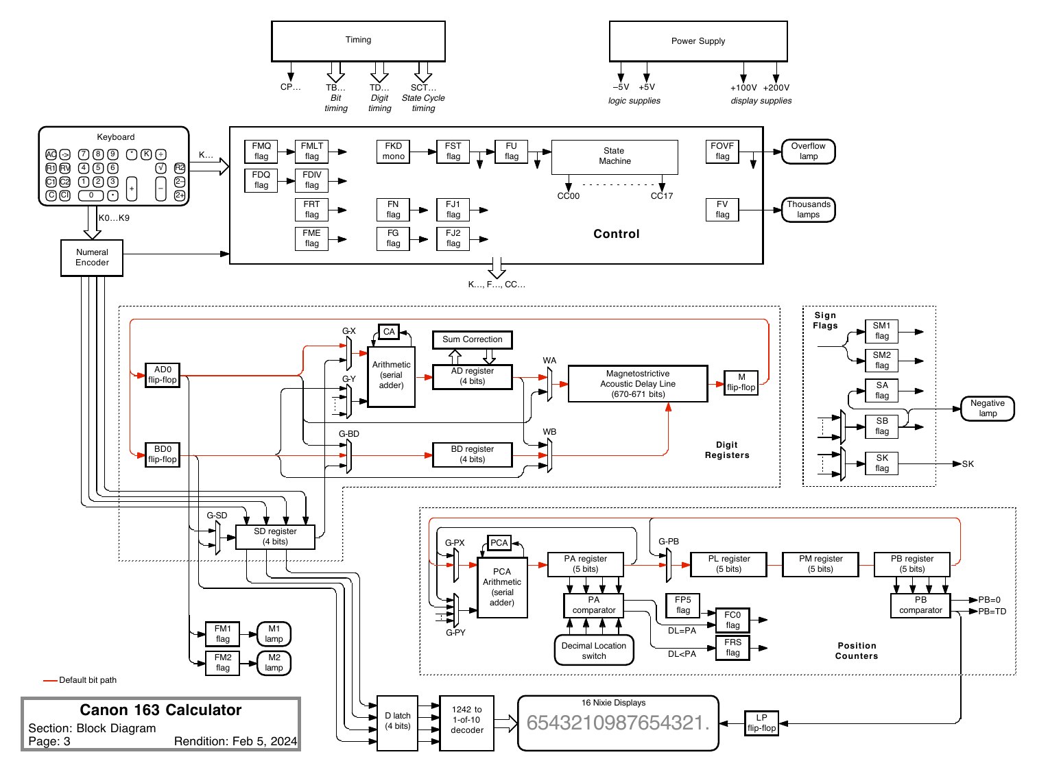
The Canon 163’s two display supplies, +200 V and +100 V, are exactly this arrangement: the higher feeds the anodes and the lower holds the unlit cathodes up. The Casio 121-B’s +180 V and +84 V do the same job.
4.3 Cathode drivers and decoders
Each cathode needs a switch, and something must decide which of the ten switches to close. There were three generations of solution.
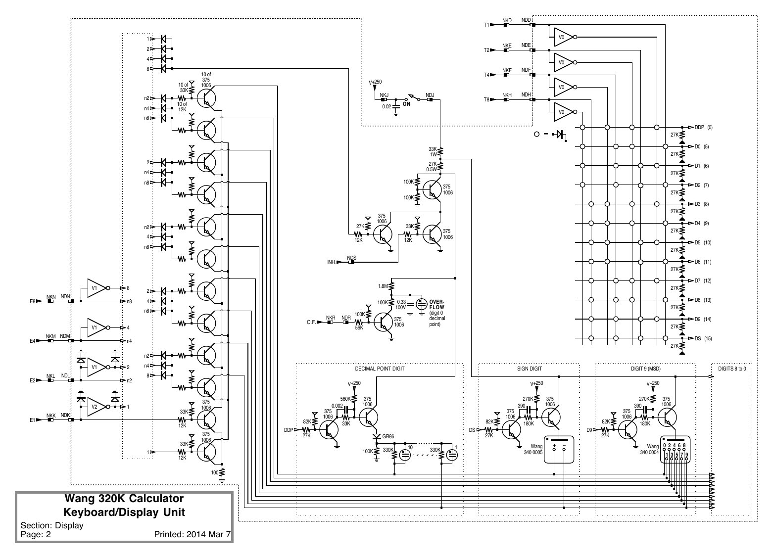
Discrete transistors and a diode decoder. In the transistor machines, the digit arrives as four binary-coded bits and a diode matrix decodes it into one of ten lines, each driving a high-voltage transistor. The Wang 320K keyboard is a clear example: Brent Hilpert’s schematic shows the four bit lines E1, E2, E4 and E8 buffered and fed through a matrix of diodes to ten cathode transistors, Wang part 375-1006, with the anode of each tube switched by its own transistor from the +250 V rail. Hilpert’s repair notes for the IME 84 and 86S use MPSA92 and MPSA42 high-voltage transistors as replacements.
No decoder at all. The ANITA Mk VIII counted in rings of ten gas tubes, already one-of-ten, and drove its Nixies directly from the counting rings; the theory volume shows how.
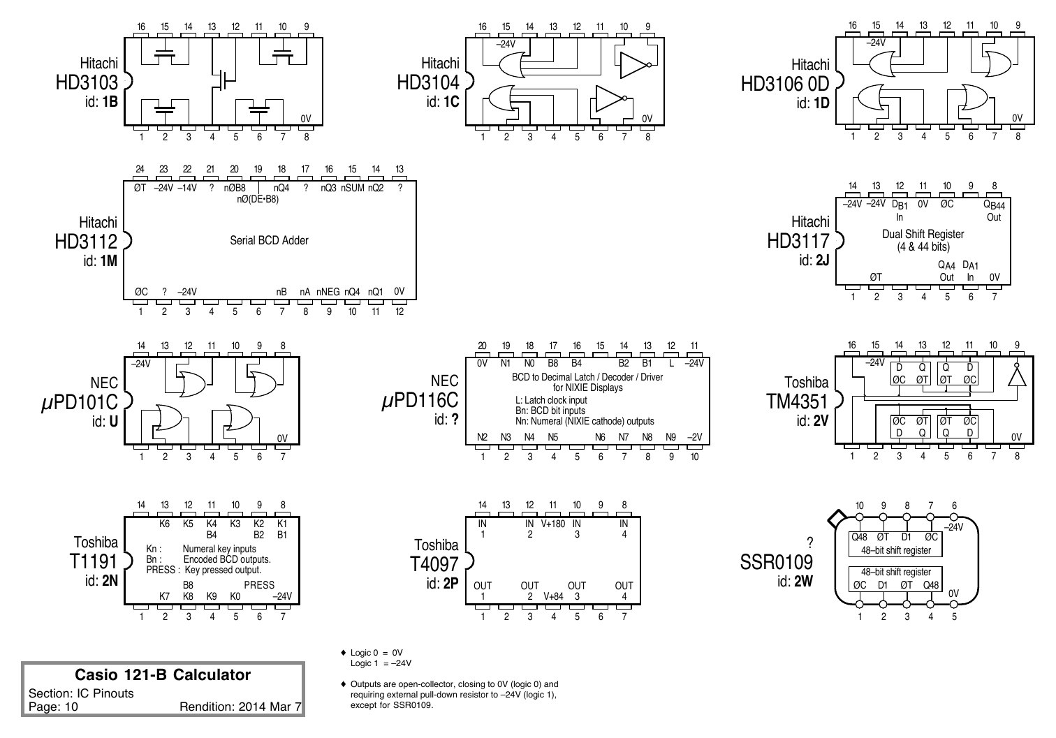
A decoder-driver chip. From the late 1960s one integrated circuit could do the whole job. In America, Texas Instruments’ 7441 and later 74141 take a four-bit BCD input and have ten open-collector outputs rated for Nixie cathodes; the Soviet K155ID1 is a copy that was still being made decades later. Hobbyist sources give the off-state rating as about 60 V for the 74141 and about 100 V for the K155ID1, which works because the tube needs only that much between lit and unlit cathodes; they also report that an invalid code, 10 to 15, blanks all the outputs. In Japan, NEC made MOS decoder-drivers for calculators: the Casio 121-B uses an NEC µPD116C, which Hilpert identifies as a “BCD to decimal latch/decoder/driver for Nixie displays”, with ten numeral outputs, a latch-clock input and four bit inputs, beside Toshiba T4097 high-voltage transistor arrays.
4.4 Static or multiplexed
The second big decision is how many decoders to have.
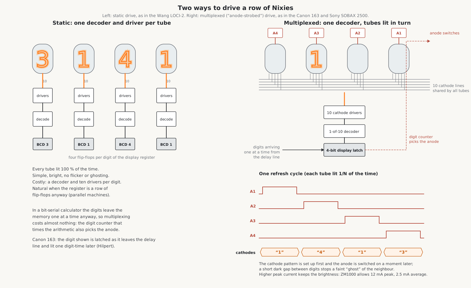
Static drive gives every tube its own decoder and ten cathode drivers, permanently connected to the four flip-flops of its digit in the display register. The tubes are lit all the time, so they are bright and steady, and there is no possibility of one digit’s image bleeding into another. The cost is a decoder and ten drivers per digit: 120 driver transistors for a 12-digit machine. Static drive was natural in machines whose registers were rows of flip-flops anyway. The Wang LOCI-2 is the example: the Old Calculator Web Museum describes separate decoder and driver circuits for each Nixie, fed from the four BCD flip-flops of the matching digit of the W register. The LOCI-2 uses the arrangement to show a cursor: while a number is being keyed in, the tube where the next digit will appear is blanked.
Multiplexed drive, which the makers called time-sharing and Burroughs called anode strobing, connects the like cathodes of every tube together: all the 0s on one line, all the 1s on another, ten lines in all plus the decimal points. One decoder and one set of ten cathode drivers serve the whole row. Each tube’s anode is switched separately, and the machine lights the tubes one at a time, setting up the cathode lines for digit 1 and switching on tube 1’s anode, then digit 2 and tube 2, and so on, fast enough that the eye sees a steady row.
Multiplexing suited the bit-serial calculators perfectly. Their numbers live in a delay line, a magnetic core array or a MOS shift register, and come past one digit at a time anyway. The display needs only a four-bit latch to catch each digit as it passes, and the digit counter that times the arithmetic also chooses which anode to switch on. In the Canon 163 the displayed register circulates through a short loop of the delay line; as each digit leaves the line it is caught in a 4-bit display latch, decoded from Canon’s 1-2-4-2 code to one-of-ten, and lights the cathodes, while the matching tube’s anode is switched on one digit-time later. In the Sony SOBAX 2500 the digit is parallel-loaded into a display latch at the end of each digit period and held steady through the next “while one Nixie anode is enabled”. In the IME 84, each digit is read out of the core memory in turn, and one phase of every digit period presents it to its Nixie.
Multiplexing has a cost in brightness. With N tubes, each is lit only 1/N of the time, one-sixteenth in a 16-digit machine, so it must run at a higher peak current to look as bright. The Philips ZM1000 allows 12 mA peak in pulsed use provided the average stays at 2.5 mA, and requires pulses of at least 100 µs. Burroughs recommended only its long-life tubes for pulsed operation. A tube also needs a little time to strike each time its anode is switched on, which is why some multiplex tubes have a primer electrode, kept glowing faintly to supply ions.
4.5 A worked example: the Friden EC-1115
Friden’s service manual of December 1969 for the Hitachi-built EC-1115 describes a complete MOS-era multiplexed display in a few pages, and it shows how much ingenuity went into saving parts.
The machine’s logic is Hitachi PMOS running between 0 and −24 V, and it has no 200 V supply at all. Its supplies are +103 V and −103 V. Each of the twelve tubes has its own anode capacitor, charged to about 206 V between the two rails. When a tube’s turn comes, its anode transistor switches on and pulls one plate of the capacitor from −103 V to about −5 V, a jump of 98 V. The other plate, at +103 V, jumps with it, and the anode receives about 200 V for as long as the tube is lit. The capacitor is, in effect, a one-shot charge pump for each digit.
The twelve anodes are switched in step with the digit times of the register: digit times DT5 to DT16 correspond to the twelve displayed digits, from the least significant to the most. Ten cathode transistors, K0 to K9, are shared by all twelve tubes, as in any multiplexed display.
The decimal point gets a time slot of its own. During digit time DT1 the register delivers not a digit but the decimal-point position, and a control transistor holds every anode off. At the end of DT1 the position is latched into the cathode decoder, and during DT2 all twelve anodes are switched on at once while only one of twelve decimal-point cathodes, P1 to P12, is driven: only the tube whose point is lit glows, and only at its point. The manual counts 22 cathode driver transistors, ten for the numerals and twelve for the points. To save base drive, the numeral and point transistors share their base inputs in pairs and are told apart by two separate emitter buses, one switched on during the numeral times and the other during the point time.
4.6 Ghosts
A multiplexed display can show ghosts: a faint image of the neighbouring tube’s digit in each tube. They come from switching the anode and cathode lines at the same instant, so that for a moment one tube’s anode is on while the next digit’s cathode is already selected, and from the stray capacitance of the long shared lines holding charge from one digit to the next. The cures are to set up the cathode lines first and switch the anode on a moment later, to leave a short dark gap between digits, and to fit bleed resistors on the lines. The Burroughs B-5750, designed for calculators, was advertised as having “no lead glow, even with the overdrive that’s common in time-sharing circuits that use anode strobing”. Parasitic glow and ghosts are worst when the tubes are cold and fade as they warm up.
In a static machine a ghost has a different cause: a leaky driver transistor that lets a little current through an unlit cathode. Hilpert found exactly this in a Wang 320K, where a faint “0” in every digit came from a cathode driver leaking about 120 kΩ from collector to emitter; the repair volume collects such cases.
4.7 Decimal points, signs and separators
Decimal points were handled in two ways. Many tubes have one or two small decimal-point cathodes, a dot beside the numeral, lit like any other cathode; in multiplexed machines a counter holding the position of the point is compared with the digit counter, and when they match the decimal-point line is driven. The Canon 163 and Sony 2500 work this way, with right-hand points: to show four decimal places the Sony lights the point of the fifth tube from the right. Other machines put separate neon lamps between the tubes: the Wang LOCI-2 and the Sharp CS-10A do. The Burroughs B-5441 has points on both sides; when a point lights on its own it needs its own cathode resistor and at least 100 V of pre-bias.
The sign of a number was shown by a separate sign tube (the Wang LOCI-2 and Sharp Compet 20, whose sign tube is an NEC CD-59), by a lamp (the Friden EC-1115’s sign indicator), or not at all: the ANITA shows a negative number as its ten’s complement, so that −1 appears as twelve 9s. The Sony 2500 makes thousands separators by lighting decimal points at one-eighth of the normal duty cycle, so that they glow dimmer than a true decimal point.
4.8 Leading zeros
A 16-digit display showing 0000000000003.25 is hard to read. Early machines lived with it: the ANITA, the Wang LOCI-2 and the Toshiba BC-1411 have no zero suppression. The Sony SOBAX ICC-500 of 1967 was unusual in blanking leading zeros. In the Sony 2500, the logic marks the zeros to be shown: while the machine waits for a key, it rewrites those zeros in the display register to an otherwise unused code, 1000, and leaves the leading zeros as true 0s, which the decoder displays as nothing. The SCM Cogito 412 took a middle course and dimmed its insignificant zeros to a quarter of full brightness, keeping the display’s length visible while making the number stand out.
4.9 What this means for repair
The display circuits are the part of a Nixie calculator most likely to need work, and the theory above tells you where to look:
- One tube dark, others fine, in a multiplexed machine: that tube’s anode driver, its anode resistor, or the tube itself. The cathode lines are shared, so the decoder is not at fault.
- The same numeral missing in every tube: the shared cathode line or its driver.
- A faint extra digit in one or every tube: a leaky cathode or anode driver; or, in a multiplexed machine, ghosting.
- All tubes dark: the high-voltage supply, or the timing that strobes the anodes. A dead display is quite often a clock or timing fault rather than a high-voltage fault.
- Haze round every lit numeral: the pre-bias rail is low.
- Dim, flickering or patchy numerals: the high-voltage supply is low, the series resistors have drifted, or the tube is worn.
The repair volume works through each of these.
Comments (0)