CRT Calculators · Volume 3
Theory of Operation: The Friden EC-130 in Depth
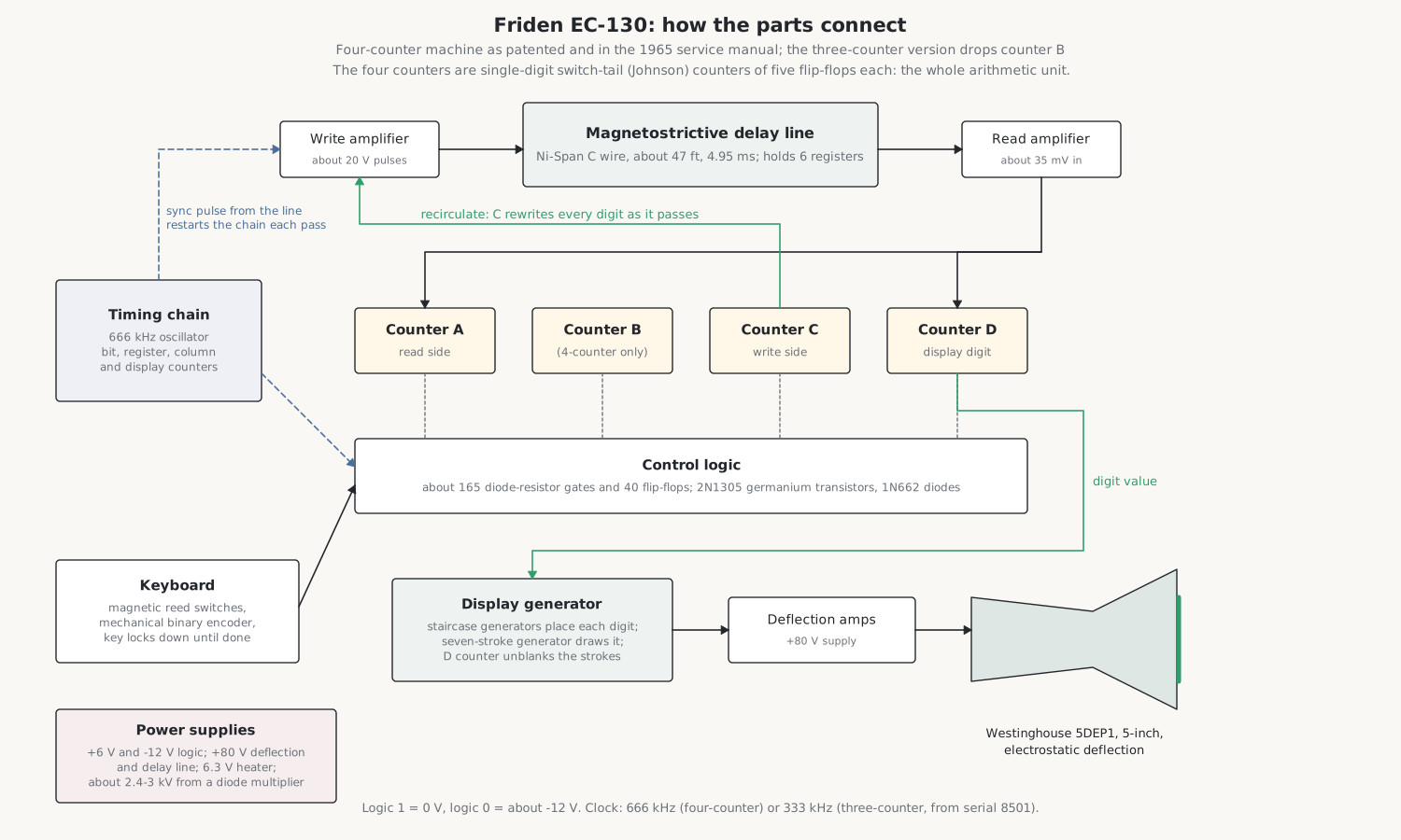
The Friden EC-130 is the machine to understand first. It was the first of the type to sell in numbers, the later Fridens are the same design in integrated circuits, and its documentation survives in full: a 161-page factory service manual of September 1965, the logic schematics, a 48-page engineering report on the delay line, and Robert Ragen’s patents. This volume follows those documents through the logic, the memory and the arithmetic. The next volume does the same for the CRT and its circuits.
Its design rests on three ideas, each unusual today:
- The numbers are stored as sound. All six registers circulate as pulses travelling along about 47 feet of nickel-alloy wire, and come round every five thousandths of a second.
- A digit is a count of pulses. A 7 is seven pulses, not a binary code, so a counter can add simply by counting.
- The whole arithmetic unit is four one-digit counters. The machine never holds more than a few digits outside the wire at once; everything else is timing.
3.1 The logic: diodes, germanium and negative voltages
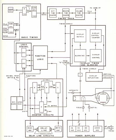
The EC-130 was designed in 1961–63, before integrated circuits were affordable. Its logic is diode-resistor gating (AND and OR functions made from silicon diodes, mostly 1N662, and resistors), with germanium PNP transistors, mostly 2N1305, as inverters, emitter-followers and flip-flops. Silicon transistors were judged too expensive. There are about 165 gates and 40 flip-flops; the EC-132 has 324 transistors in its logic alone.
Because the transistors are PNP, the logic runs on negative voltages: 0 V is a logical 1 and about −12 V is a logical 0. The schematics use boxes marked A (AND), O (OR) and I (inverter), EF for emitter-follower, split boxes for flip-flops, and diamond inputs for “AC gates”, which respond to an edge rather than a level and are how the counters are stepped.
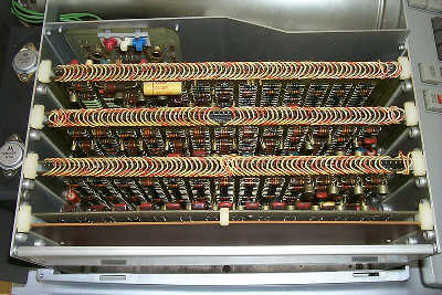
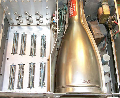
The logic is on seven boards of about 12 × 5 inches in the three-counter EC-130 (eight in the four-counter machine and in the EC-132), mostly in pairs joined by hand-soldered jumpers across the top. The supplies are +6 V and −12 V for the logic, 80 V for the deflection amplifiers and the delay-line driver, 6.3 V for the CRT heater, and about −2,400 V for the tube.
3.2 Counting instead of adding: the switch-tail counters
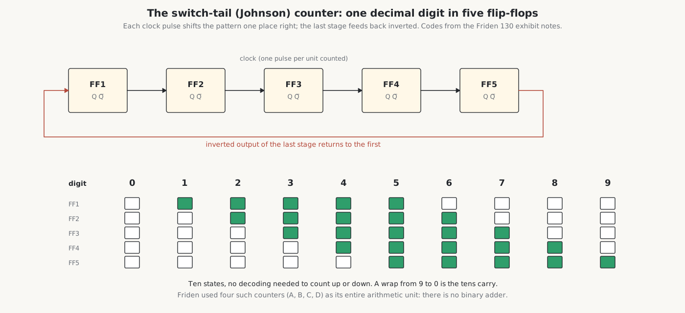
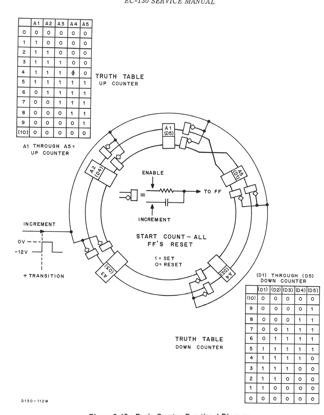
Each of the four counters, named A, B, C and D, holds one decimal digit in five flip-flops connected as a switch-tail or Johnson counter: a shift register whose last stage feeds back, inverted, to the first. Starting from all zeros, each clock pulse shifts a 1 in from the left until all five are set, and then shifts 0s in, so the counter passes through ten distinct states before it repeats:
Table 1 — Each of the four counters, named A, B, C and D, holds one decimal digit in five flip-flops connected as a switch-tail or Johnson counter: a shift register whose last stage feeds back, inverted, to the first. Starting from all zeros, each clock pulse shifts a 1 in from the left until all five are set, and then shifts 0s in, so the counter passes through ten distinct states before it repeats
| digit | 0 | 1 | 2 | 3 | 4 | 5 | 6 | 7 | 8 | 9 |
|---|---|---|---|---|---|---|---|---|---|---|
| flip-flops 1–5 | 00000 | 10000 | 11000 | 11100 | 11110 | 11111 | 01111 | 00111 | 00011 | 00001 |
Ten states in five flip-flops is less efficient than binary, which needs only four, but it has two great advantages for a machine like this. Each state differs from the next in one flip-flop only, so the counter can be stepped up or down with simple gating and decoded with two-input gates. And a step from 9 back to 0 is easy to detect: that is the carry. The patents call these counters “digisters”.
The roles of the counters, from the patents and the service manual:
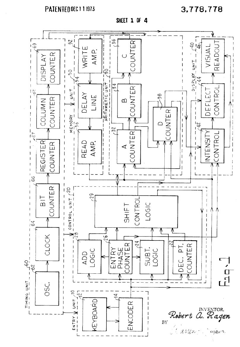
- A takes each digit as it arrives from the delay line’s read amplifier.
- C sends each digit back into the line through the write amplifier. Every digit passes through the counters and is rewritten on every pass, which is how a number can be changed: count extra pulses into a counter on its way through, and the digit written back is different.
- D also receives digits from the read side and holds the digit being displayed: the CRT circuits read D to decide which strokes of a digit to light.
- B is an extra counter used in some operations on the first machines. Friden found it could do without it, and from serial 8501 the “three-counter” EC-130 has no B (see below).
There is no adder in the usual sense. With digits stored as pulse counts, adding a digit of one register to a digit of another means counting both sets of pulses into the same counter. If the counter passes 9, a carry is remembered and added to the next digit as it comes by.
3.3 The delay line: memory made of sound
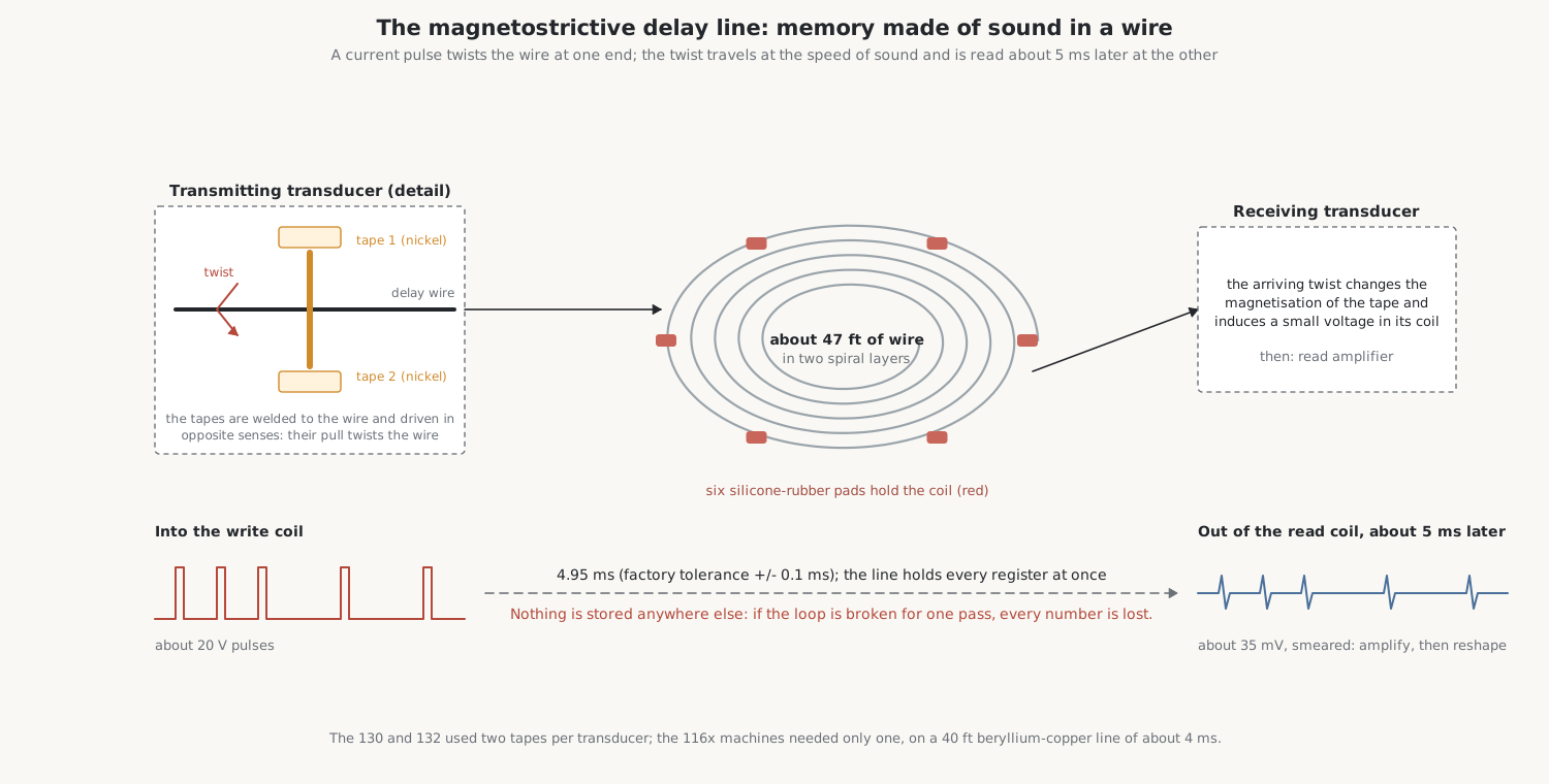
A magnetostrictive delay line stores data as mechanical waves travelling along a wire. Magnetostrictive materials such as nickel change shape slightly when magnetised, and conversely change their magnetisation when stressed. So a current pulse in a coil round a nickel tape can launch a tiny mechanical pulse into a wire, and the same pulse, arriving at the far end, can induce a voltage in a second coil. The wire is a pipe for sound: whatever is put in at one end comes out at the other a fixed time later, and if what comes out is amplified, reshaped and put back in, the pattern circulates indefinitely.
The Friden line is a wire of Ni-Span C, a nickel-iron-chromium alloy chosen because its elasticity barely changes with temperature, so the delay stays constant. Unwound it is about 47 feet long (the service manual says “approximately 50”), wound in two spiral layers on six silicone-rubber pads inside an aluminium housing in the base. The pulses are torsional: a twist, not a push. At the transmitting end two magnetostrictive nickel tapes are welded to opposite sides of the wire and driven in opposite senses by their coils, so that their pull twists it; at the receiving end the arriving twist changes the magnetisation of the tapes and induces a voltage in their coils. Welding the tapes to the wire was so delicate that at first only one toolmaker at Friden, Rolf Magnussen, could do it.
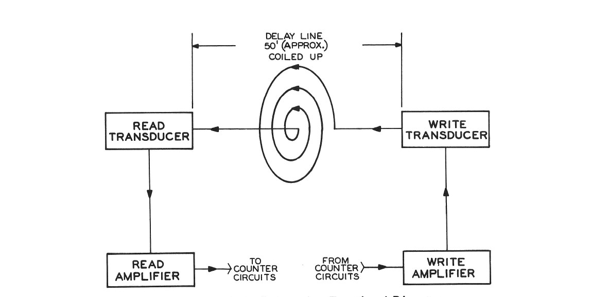
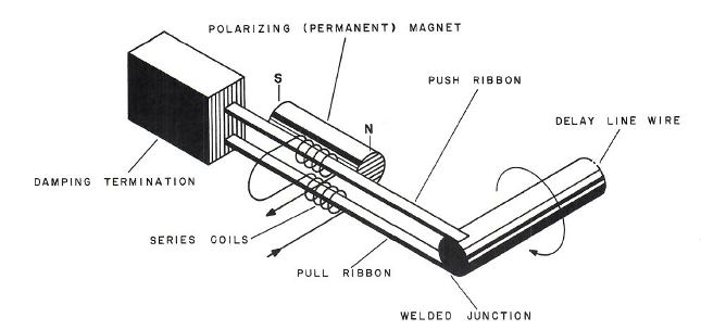
The numbers that matter:
- Delay: 4.95 ms ± 0.1 ms (the EC-132’s line is marked 5.02 ms). From the length and the delay, the twist travels at about 2,900 metres a second (calculated), a little under nine times the speed of sound in air.
- Drive: about 20 V pulses into the write coil.
- Output: about 35 mV from the read coil, small and smeared. The read amplifier lifts it to logic level and a shaper turns it back into clean pulses; its gain is set with a potentiometer to give a 4 V peak signal at a test point (see the repair volume).
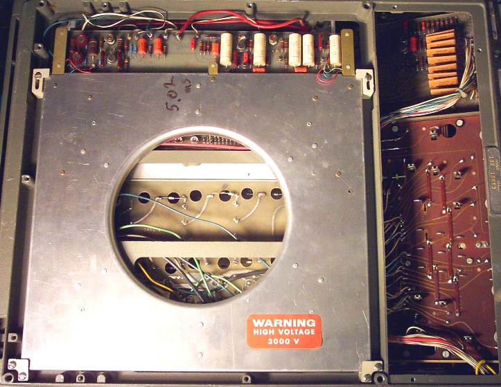
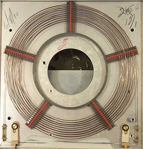
The delay line is the reason the machine was possible at all. Friden estimated that holding its registers in flip-flops would have taken more than 600 transistors; the line holds them all in one coil of wire. Its weakness is that it is the only store. Nothing is kept anywhere else, so if the loop is broken for a single pass, every number in the machine is gone.
3.4 Keeping time with a wire
A delay line’s length cannot be made exact, and it changes slightly with temperature. Ragen’s answer, set out in US patent 3,778,778 (“Calculator with self-synchronous recirculating memory”), was to let the line keep the time.
The clock is a free-running oscillator of about 666 kHz, whose exact frequency does not matter: the patent says a drift of 6% has no ill effect. It drives a chain of counters (bit, register, column and display) that divide each pass into its time slots. At the start of each train of data the line carries a sync pulse in column C0. When the sync pulse comes out of the read amplifier, it restarts the timing chain from zero, and at the end of the data the chain stops and waits for the next sync pulse. So the timing re-locks to the wire once on every circulation, and the length of the line does not need to be trimmed to the microsecond.
3.5 How a number lies in the wire
Ragen’s patents describe the train of data that circulates in the line, and the service manual’s timing confirms it:
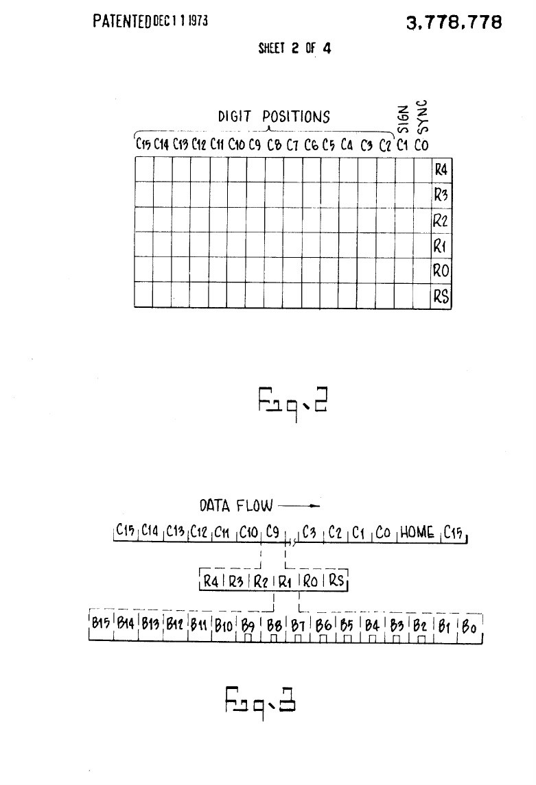
- 16 columns, C0 to C15. C0 carries the sync pulse, C1 the signs, and C2 onwards the digit places, least significant first; there are 13 digit places.
- In each column, 6 registers side by side: RS, R0, R1, R2, R3 and R4. As the patent puts it, the cells of a column are adjacent, while the cells of a register recur at regular intervals. The same digit place of every register passes by in succession, so a counter can combine the corresponding digits of two registers within one column time.
- Each register cell has 16 bit slots. A digit is written as that number of pulses in slots B2 to B10: no pulses for 0, nine for 9. A pulse in a register’s C1 cell means the number is negative.
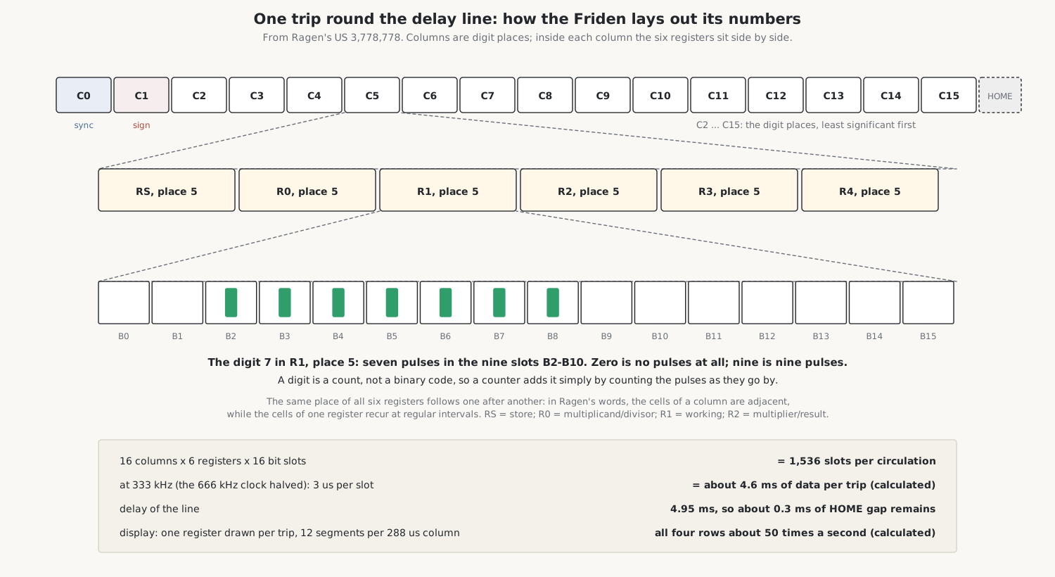
The register roles in the patents: R0 holds the multiplicand or divisor; R1 is the working register, the bottom line of the display, where numbers are entered; R2 receives the multiplier and then the product or quotient; R1 to R4 are the four registers shown on the screen, the stack; RS is the store register for STORE and RECALL.
The times fall straight out of the clock. The 666 kHz oscillator halved gives a bit time of 3 µs; 16 bits make a register cell of 48 µs; six cells make a column of 288 µs; 16 columns make about 4.6 ms, which fits inside the 4.95 ms line with time to spare for the HOME gap before the next sync pulse. These figures are my arithmetic from the patent’s layout, but the service manual uses the same 48 µs and 288 µs.
3.6 Moving numbers: the stack
The four visible registers behave as a stack. ENTER pushes the bottom number up, an operation pops the stack, and REPEAT copies the bottom number. In a delay-line machine, moving a number from one register to another means moving it in time: the registers are 48 µs apart in the train, so delaying every digit of R1 by one register slot puts it into R2.
The service manual describes it in exactly those terms. To shift up, each digit is passed from counter A to counter D and held in D for one register time before being written back, so it re-enters the line one register later. To shift down, data is shifted A to C instead of A to D, and because C is written back one register time sooner, each register’s contents move down one place: R4 to R3, R3 to R2, R2 to R1. A whole stack shift takes one pass of the line, about 5 ms.
3.7 Arithmetic
All arithmetic is done digit by digit, least significant first, as the digits stream past, with a carry or borrow remembered from one column to the next.
- Addition. The stack shifts down and the corresponding digits of R0 and R1 are counted together in one pass, carries going forward to the next column.
- Subtraction is done by adding the complement. If the result is negative, the machine complements it back on a second pass and sets the sign, so the answer is always shown as a true figure with a minus sign, never as a complement.
- Multiplication is repeated addition. For each digit of the multiplier, the multiplicand is added that many times, and then shifted one place, as on a mechanical calculator.
- Division is repeated subtraction. The divisor is subtracted until the remainder goes negative, the last subtraction is undone, and 1 is counted into the quotient for each successful subtraction, place by place. Dividing 9,999,999,999,999 by 1 takes about two seconds. Dividing by zero never ends: the machine loops with the display blanked until it is cleared.
- The decimal point is fixed by the thumbwheel. A four-flip-flop counter is loaded with the 16’s complement of the setting, and each left shift steps it until it reaches zero, so that numbers are aligned to the chosen number of decimal places.
The machine blanks its display during arithmetic and redraws it when the operation is finished, because the delay line’s time is spent on the calculation.
3.8 The EC-132’s square root
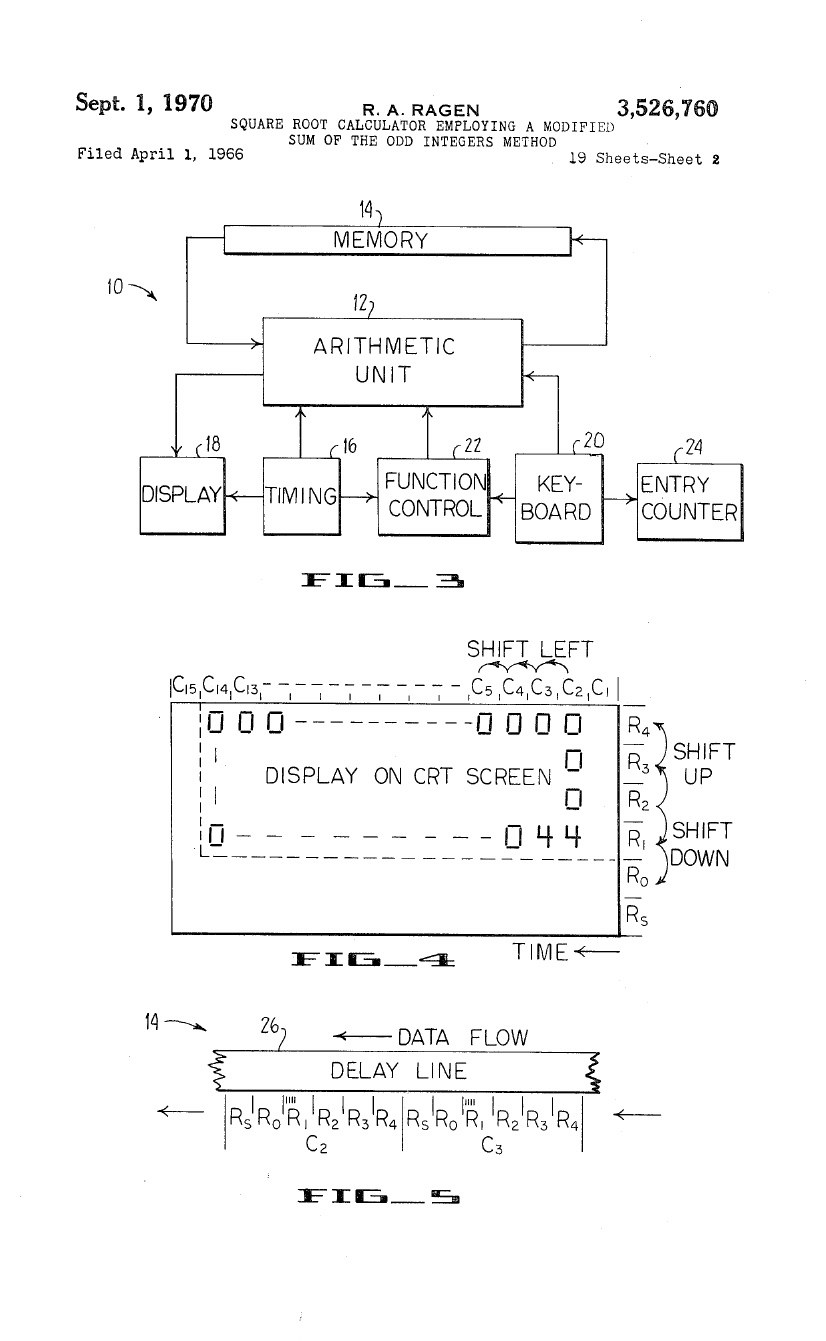
The EC-132 adds a square-root key, using a method from Friden’s mechanical SRQ calculator and set out in Ragen’s US patent 3,526,760. It rests on the fact that the sum of the first n odd numbers is n²: 1 + 3 + 5 + … + (2n − 1) = n². Working on the radicand two digits at a time from the left, the machine subtracts successive odd numbers until the remainder would go negative; the count of subtractions is the next digit of the root, and the last odd number subtracted is carried, shifted, into the next pair. The root comes out as (N + 1) / 2, where N is the last odd number subtracted. Finding √4 takes about a tenth of a second, and √9,999,999,999,999 about 2.5 seconds. A negative argument’s sign is ignored. Friden’s square-root service notes explain it for technicians.
3.9 Four counters to three
From serial 8501 of the EC-130, and an equivalent serial of the EC-132, Friden removed the B counter and its control logic. The three-counter machine keeps A on the read side, C on the write side and D for the display, and does with them everything the four-counter machine did. The clock drops from 666 to 333 kHz because a divider stage was removed. On a four-counter machine the bottom register is drawn twice in each display cycle and looks brighter; on a three-counter machine all four lines are equally bright. The 1965 service manual describes the four-counter machine, and a 26-page supplement covers the three-counter version.
3.10 The keyboard
The EC-130 has only the ten digit keys and a handful of operation keys. Each key works a magnetic reed switch through a mechanical binary encoder of code bars, so a key press arrives at the logic as a code, not as one wire per key. An operation key locks down until the operation is finished, so the operator cannot interrupt the machine halfway through a pass.
3.11 What went wrong in production
Two problems delayed the launch by about six months and dogged the early machines. The plated-through holes on the boards were unreliable, and in the field they were reinforced by hand-soldering; one engineer blamed nearly all early field failures on them. And static discharge from the high-voltage CRT section caused random wrong answers. Friden’s 35 service letters of 1964–68, all in the Library, record these and later fixes.
3.12 Documents
- EC-130 Service Manual, September 1965: the source for almost everything in this volume.
- Field Service Manual, August 1964
- Logic schematic, four-counter and three-counter; EC-132 logic schematic
- Delay-line engineering report, 1964
- Friden’s EC-130 and EC-132 Master Design Documentation printouts: the logic as Friden’s computer listed it.
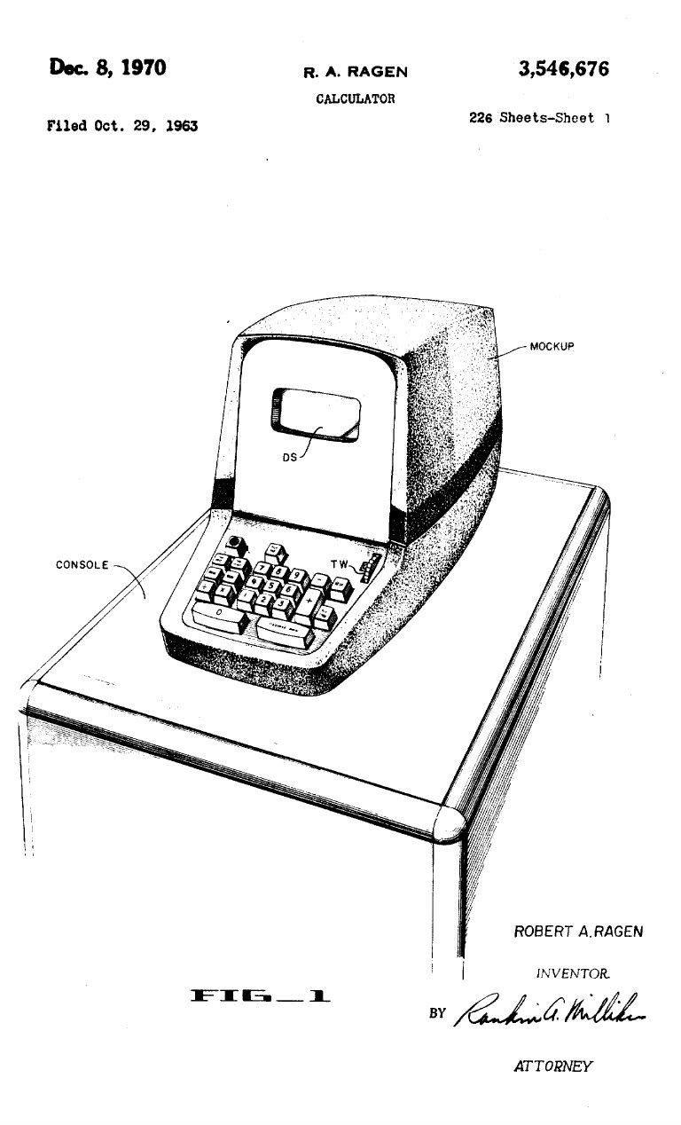
- Patents: US 3,546,676, US 3,523,282, US 3,634,666, US 3,778,778, US 3,526,760.
Comments (0)